HP Cluster Platform Introduction v2010 HP Cluster Platform Workgroup System To - Page 33
A-2 Example Configuration 2: 2.7kVA, N+N Redundant Enclosure with 16A PDU, C20-C13
 |
View all HP Cluster Platform Introduction v2010 manuals
Add to My Manuals
Save this manual to your list of manuals |
Page 33 highlights
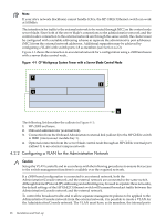
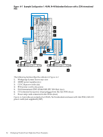
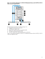
Figure A-2 Example Configuration 2: 2.7kVA, N+N Redundant Enclosure with 16A PDU, C20-C13 Power Cords (not supplied by HP) 2 33 1 2 3 3 5 4 5 4 The following list describes the callouts in Figure A-2: 1. Workgroup System Tower rear view 2. 1200W power supplies (six) 3. Four C20-C13 power cords (not supplied by HP). 4. PDU power cords to site power (two) 5. 16A PDU, 252663-B24 with detachable power cords (two) Figure A-3 provides an example of a 3kVA, N+1 redundant enclosure with a 16A PDU, C20-C13 cords (not supplied by HP). 33
-
 1
1 -
2
-
3
-
4
-
5
-
6
-
7
-
8
-
9
-
10
-
11
-
12
-
13
-
14
-
15
-
16
-
17
-
18
-
19
-
20
-
21
-
22
-
23
-
24
-
25
-
26
-
27
-
 28
28 -
 29
29 -
 30
30 -
 31
31 -
 32
32 -
 33
33 -
 34
34 -
 35
35 -
 36
36 -
 37
37 -
 38
38 -
39
-
40
-
41
-
42
-
43
-
44
 |
 |

Figure A-2 Example Configuration 2: 2.7kVA, N+N Redundant Enclosure with 16A PDU, C20-C13
Power Cords (not supplied by HP)
5
4
5
4
2
2
1
3
3
3
3
The following list describes the callouts in
Figure A-2
:
1.
Workgroup System Tower rear view
2.
1200W power supplies (six)
3.
Four C20-C13 power cords (not supplied by HP).
4.
PDU power cords to site power (two)
5.
16A PDU, 252663-B24 with detachable power cords (two)
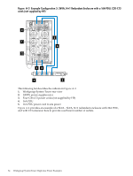
Figure A-3
provides an example of a 3kVA, N+1 redundant enclosure with a 16A PDU, C20-C13
cords (not supplied by HP).
33