HP ENVY 14-3010nr HP ENVY14 SPECTRE Maintenance and Service Guide IMPORTANT! T - Page 54
Remove the Phillips PM2.0×3.6 screw, Turn the top cover upside down, with the front toward you.
 |
View all HP ENVY 14-3010nr manuals
Add to My Manuals
Save this manual to your list of manuals |
Page 54 highlights
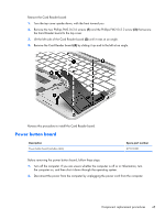
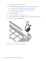
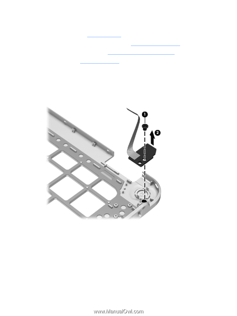
3. Disconnect all external devices from the computer. 4. Remove the battery (see Battery on page 32), and then remove the following components: a. Solid-state drive connector board cable (see Solid-state drive on page 34) b. Card Reader board cable (see Card Reader board cable on page 36) c. Top cover (see Top cover on page 39) Remove the power button board: 1. Turn the top cover upside down, with the front toward you. 2. Remove the Phillips PM2.0×3.6 screw (1) that secures the power button board to the top cover. 3. Remove the power button board (2) and cable. Reverse this procedure to install the power button board. 46 Chapter 4 Removal and replacement procedures
-
 1
1 -
2
-
3
-
4
-
5
-
6
-
7
-
8
-
9
-
10
-
11
-
12
-
13
-
14
-
15
-
16
-
17
-
18
-
19
-
20
-
21
-
22
-
23
-
24
-
25
-
26
-
27
-
28
-
29
-
30
-
31
-
32
-
33
-
34
-
35
-
36
-
37
-
38
-
39
-
40
-
41
-
42
-
43
-
44
-
45
-
46
-
47
-
48
-
 49
49 -
 50
50 -
 51
51 -
 52
52 -
 53
53 -
 54
54 -
 55
55 -
 56
56 -
 57
57 -
 58
58 -
 59
59 -
60
-
61
-
62
-
63
-
64
-
65
-
66
-
67
-
68
-
69
-
70
-
71
-
72
-
73
-
74
-
75
-
76
-
77
-
78
-
79
-
80
-
81
-
82
-
83
-
84
-
85
-
86
-
87
-
88
-
89
-
90
-
91
-
92
-
93
-
94
-
95
-
96
-
97
 |
 |
3.
Disconnect all external devices from the computer.
4.
Remove the battery (see
Battery
on page
32
), and then remove the following components:
a.
Solid-state drive connector board cable (see
Solid-state drive
on page
34
)
b.
Card Reader board cable (see
Card Reader board cable
on page
36
)
c.
Top cover (see
Top cover
on page
39
)
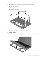
Remove the power button board:
1.
Turn the top cover upside down, with the front toward you.
2.
Remove the Phillips PM2.0×3.6 screw
(1)
that secures the power button board to the top cover.
3.
Remove the power button board
(2)
and cable.
Reverse this procedure to install the power button board.
46
Chapter 4
Removal and replacement procedures