HP ENVY 14-3010nr HP ENVY14 SPECTRE Maintenance and Service Guide IMPORTANT! T - Page 66
One Phillips PM2.0×5.7
 |
View all HP ENVY 14-3010nr manuals
Add to My Manuals
Save this manual to your list of manuals |
Page 66 highlights
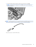
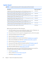
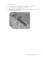
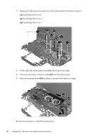
4. Remove the following screws that secure the system board to the base enclosure: (1) Five Phillips PM2.0×3.8 (2) Four Phillips PM2.0×4.6 (3) One Phillips PM2.0×5.7 5. Lift the right side of the system board (1) until it rests at an angle. 6. Disconnect the power connector cable (2) from the system board. 7. Remove the system board (3) by sliding it up and to the right at an angle. Reverse this procedure to install the system board. 58 Chapter 4 Removal and replacement procedures
-
 1
1 -
2
-
3
-
4
-
5
-
6
-
7
-
8
-
9
-
10
-
11
-
12
-
13
-
14
-
15
-
16
-
17
-
18
-
19
-
20
-
21
-
22
-
23
-
24
-
25
-
26
-
27
-
28
-
29
-
30
-
31
-
32
-
33
-
34
-
35
-
36
-
37
-
38
-
39
-
40
-
41
-
42
-
43
-
44
-
45
-
46
-
47
-
48
-
49
-
50
-
51
-
52
-
53
-
54
-
55
-
56
-
57
-
58
-
59
-
60
-
 61
61 -
 62
62 -
 63
63 -
 64
64 -
 65
65 -
 66
66 -
 67
67 -
 68
68 -
 69
69 -
 70
70 -
 71
71 -
72
-
73
-
74
-
75
-
76
-
77
-
78
-
79
-
80
-
81
-
82
-
83
-
84
-
85
-
86
-
87
-
88
-
89
-
90
-
91
-
92
-
93
-
94
-
95
-
96
-
97
 |
 |
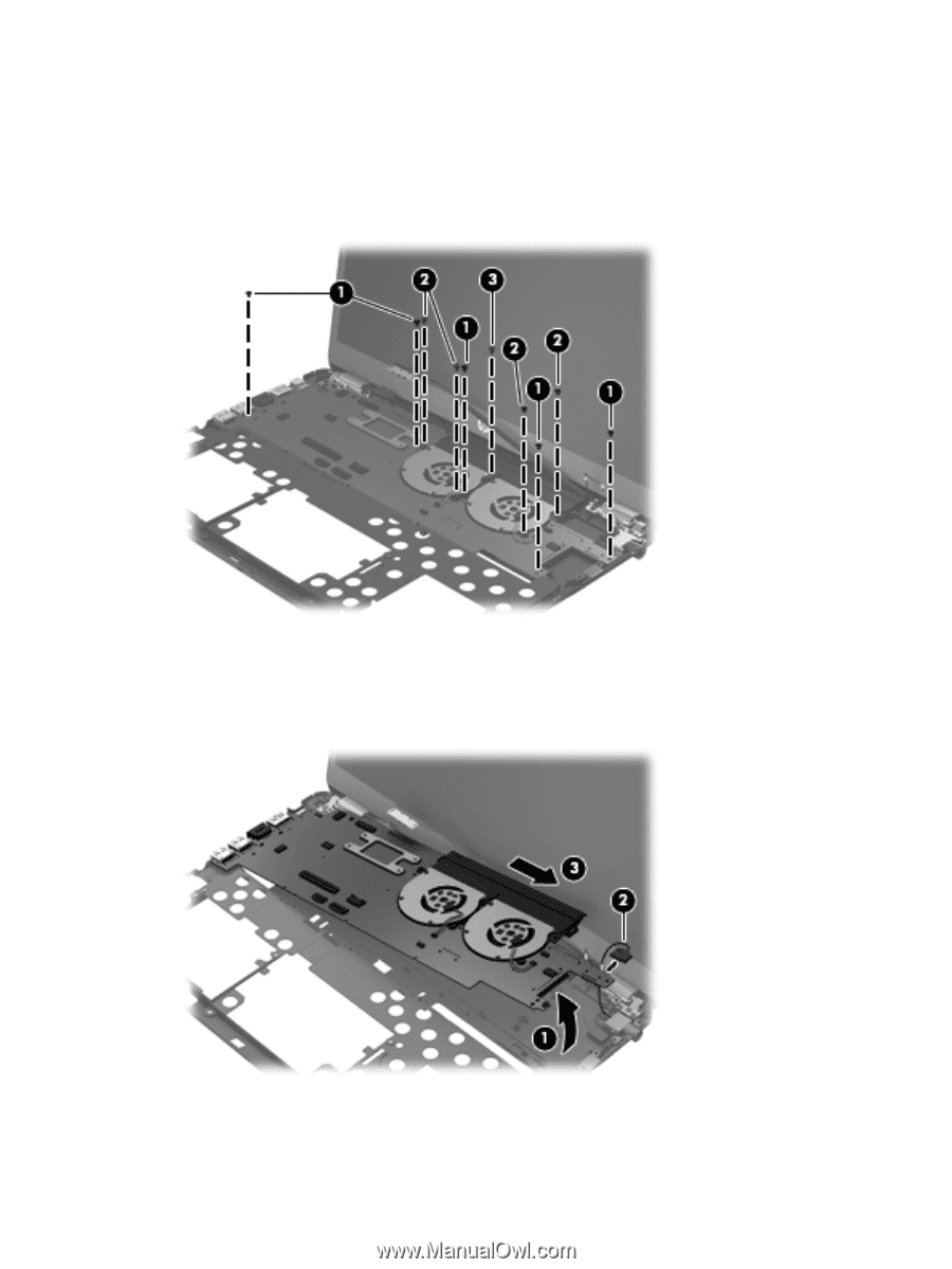
4.
Remove the following screws that secure the system board to the base enclosure:
(1)
Five Phillips PM2.0×3.8
(2)
Four Phillips PM2.0×4.6
(3)
One Phillips PM2.0×5.7
5.
Lift the right side of the system board
(1)
until it rests at an angle.
6.
Disconnect the power connector cable
(2)
from the system board.
7.
Remove the system board
(3)
by sliding it up and to the right at an angle.
Reverse this procedure to install the system board.
58
Chapter 4
Removal and replacement procedures