HP ENVY 14-3010nr HP ENVY14 SPECTRE Maintenance and Service Guide IMPORTANT! T - Page 64
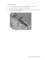
System board, Disconnect the RTC battery cable from the system board see
 |
View all HP ENVY 14-3010nr manuals
Add to My Manuals
Save this manual to your list of manuals |
Page 64 highlights
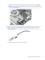
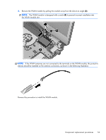
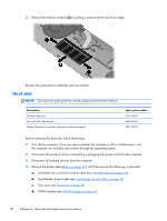
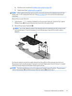
System board NOTE: The system board spare part kit includes replacement thermal material. Description Spare part number Equipped with the Intel HM76 chipset and Intel Core i7-3667U 2.0-GHz processor for use in all countries and regions except the People's Republic of China (4.0-MB L3 cache, 17 W) 685366-001 Equipped with the Intel HM76 chipset and Intel Core i5-3317U 1.7-GHz processor for use in all countries and regions except the People's Republic of China (3.0-MB L3 cache, 17 W) 685367-001 Equipped with the Intel HM76 chipset and Intel Core i7-3667U 2.0-GHz processor for use only in 689485-001 the People's Republic of China (4.0-MB L3 cache, 17 W) Equipped with the Intel HM76 chipset and Intel Core i5-3317U 1.7-GHz processor for use only in 689486-001 the People's Republic of China (3.0-MB L3 cache, 17 W) Equipped with Intel HM65 chipset and Intel Core i7-2677M 1.80-GHz processor for use in all countries and regions except the People's Republic of China (4.0-MB L3 cache, 17 W) 675516-001 Equipped with Intel HM65 chipset and Intel Core i5-2467M 1.60-GHz processor for use in all countries and regions except the People's Republic of China (3.0-MB L3 cache, 17 W) 675517-001 Thermal Material Kit (includes replacement thermal material) 675515-001 Before removing the system board, follow these steps: 1. Turn off the computer. If you are unsure whether the computer is off or in Hibernation, turn the computer on, and then shut it down through the operating system. 2. Disconnect the power from the computer by unplugging the power cord from the computer. 3. Disconnect all external devices from the computer. 4. Remove the battery (see Battery on page 32). 5. Remove the solid-state drive connector board cable (see Solid-state drive on page 34). 6. Remove the Card Reader board cable (see Card Reader board cable on page 36). 7. Remove the top cover (see Top cover on page 39). 8. Disconnect the RTC battery cable from the system board (see RTC battery on page 48). 9. Remove the wireless audio module (see Wireless audio module on page 50). 10. Remove the WLAN module (see WLAN module on page 52). When replacing the system board, be sure that the following components are removed from the defective system board and installed on the replacement system board: ● Fans (see Fan on page 54) ● Memory module (see Memory module on page 59) ● Heat sink (see Heat sink on page 60) 56 Chapter 4 Removal and replacement procedures
-
 1
1 -
2
-
3
-
4
-
5
-
6
-
7
-
8
-
9
-
10
-
11
-
12
-
13
-
14
-
15
-
16
-
17
-
18
-
19
-
20
-
21
-
22
-
23
-
24
-
25
-
26
-
27
-
28
-
29
-
30
-
31
-
32
-
33
-
34
-
35
-
36
-
37
-
38
-
39
-
40
-
41
-
42
-
43
-
44
-
45
-
46
-
47
-
48
-
49
-
50
-
51
-
52
-
53
-
54
-
55
-
56
-
57
-
58
-
 59
59 -
 60
60 -
 61
61 -
 62
62 -
 63
63 -
 64
64 -
 65
65 -
 66
66 -
 67
67 -
 68
68 -
 69
69 -
70
-
71
-
72
-
73
-
74
-
75
-
76
-
77
-
78
-
79
-
80
-
81
-
82
-
83
-
84
-
85
-
86
-
87
-
88
-
89
-
90
-
91
-
92
-
93
-
94
-
95
-
96
-
97
 |
 |