HP ENVY 14-3010nr HP ENVY14 SPECTRE Maintenance and Service Guide IMPORTANT! T - Page 74
Remove the display assembly
 |
View all HP ENVY 14-3010nr manuals
Add to My Manuals
Save this manual to your list of manuals |
Page 74 highlights
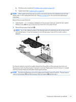
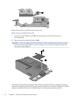
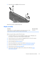
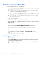
Remove the display assembly: 1. Disconnect the webcamera/microphone module cable (1) from the system board. 2. Disconnect the display panel cable (2) from the system board. 3. Release the display panel cable (3) from the heat sink. (The display panel cable is attached to the heat sink with double-sided tape.) CAUTION: Support the display assembly when removing the following screws. Failure to support the display assembly can result in damage to the display assembly and other computer components. 4. Remove the six Phillips PM2.5×5.6 screws (1) that secure the display assembly to the base enclosure. 66 Chapter 4 Removal and replacement procedures
-
 1
1 -
2
-
3
-
4
-
5
-
6
-
7
-
8
-
9
-
10
-
11
-
12
-
13
-
14
-
15
-
16
-
17
-
18
-
19
-
20
-
21
-
22
-
23
-
24
-
25
-
26
-
27
-
28
-
29
-
30
-
31
-
32
-
33
-
34
-
35
-
36
-
37
-
38
-
39
-
40
-
41
-
42
-
43
-
44
-
45
-
46
-
47
-
48
-
49
-
50
-
51
-
52
-
53
-
54
-
55
-
56
-
57
-
58
-
59
-
60
-
61
-
62
-
63
-
64
-
65
-
66
-
67
-
68
-
 69
69 -
 70
70 -
 71
71 -
 72
72 -
 73
73 -
 74
74 -
 75
75 -
 76
76 -
 77
77 -
 78
78 -
 79
79 -
80
-
81
-
82
-
83
-
84
-
85
-
86
-
87
-
88
-
89
-
90
-
91
-
92
-
93
-
94
-
95
-
96
-
97
 |
 |
Remove the display assembly:
1.
Disconnect the webcamera/microphone module cable
(1)
from the system board.
2.
Disconnect the display panel cable
(2)
from the system board.
3.
Release the display panel cable
(3)
from the heat sink. (The display panel cable is attached to
the heat sink with double-sided tape.)
CAUTION:
Support the display assembly when removing the following screws. Failure to
support the display assembly can result in damage to the display assembly and other
computer components.
4.
Remove the six Phillips PM2.5×5.6 screws
(1)
that secure the display assembly to
the base enclosure.
66
Chapter 4
Removal and replacement procedures