HP ENVY 14-3010nr HP ENVY14 SPECTRE Maintenance and Service Guide IMPORTANT! T - Page 76
that secures the power connector and bracket to, Remove the power connector cable
 |
View all HP ENVY 14-3010nr manuals
Add to My Manuals
Save this manual to your list of manuals |
Page 76 highlights
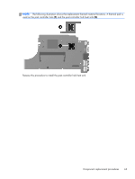
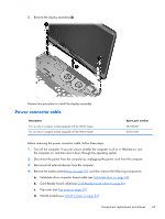
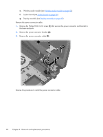
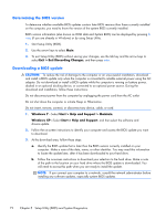
e. Wireless audio module (see Wireless audio module on page 50) f. System board (see System board on page 56) g. Display assembly (see Display assembly on page 65) Remove the power connector cable: 1. Remove the Phillips PM2.0×3.8 screw (1) that secures the power connector and bracket to the base enclosure. 2. Remove the power connector bracket (2). 3. Remove the power connector cable (3). Reverse this procedure to install the power connector cable. 68 Chapter 4 Removal and replacement procedures
-
 1
1 -
2
-
3
-
4
-
5
-
6
-
7
-
8
-
9
-
10
-
11
-
12
-
13
-
14
-
15
-
16
-
17
-
18
-
19
-
20
-
21
-
22
-
23
-
24
-
25
-
26
-
27
-
28
-
29
-
30
-
31
-
32
-
33
-
34
-
35
-
36
-
37
-
38
-
39
-
40
-
41
-
42
-
43
-
44
-
45
-
46
-
47
-
48
-
49
-
50
-
51
-
52
-
53
-
54
-
55
-
56
-
57
-
58
-
59
-
60
-
61
-
62
-
63
-
64
-
65
-
66
-
67
-
68
-
69
-
70
-
 71
71 -
 72
72 -
 73
73 -
 74
74 -
 75
75 -
 76
76 -
 77
77 -
 78
78 -
 79
79 -
 80
80 -
 81
81 -
82
-
83
-
84
-
85
-
86
-
87
-
88
-
89
-
90
-
91
-
92
-
93
-
94
-
95
-
96
-
97
 |
 |
e.
Wireless audio module (see
Wireless audio module
on page
50
)
f.
System board (see
System board
on page
56
)
g.
Display assembly (see
Display assembly
on page
65
)
Remove the power connector cable:
1.
Remove the Phillips PM2.0×3.8 screw
(1)
that secures the power connector and bracket to
the base enclosure.
2.
Remove the power connector bracket
(2)
.
3.
Remove the power connector cable
(3)
.
Reverse this procedure to install the power connector cable.
68
Chapter 4
Removal and replacement procedures