HP ENVY 14-j000 ENVY Notebook model numbers used: 14-j000 through 14-j099 Main - Page 53
the card reader board cable from the system board., to which the card reader board cable is attached
 |
View all HP ENVY 14-j000 manuals
Add to My Manuals
Save this manual to your list of manuals |
Page 53 highlights
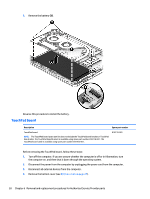
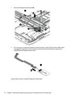
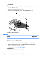
2. Release the ZIF connector (1) to which the fingerprint reader board cable is attached, and then disconnect the fingerprint reader board cable from the system board. 3. Release the fingerprint reader board cable (2) from the TouchPad board. (The fingerprint reader board cable is secured to the TouchPad board with double-sided adhesive.) 4. Release the ZIF connector (3) to which the card reader board cable is attached, and then disconnect the card reader board cable from the system board. 5. Remove the two Phillips PM2.0×3.3 screws (4) that secure the fingerprint reader board to the top cover. 6. Remove the fingerprint reader board bracket (5). Component replacement procedures 43
-
 1
1 -
2
-
3
-
4
-
5
-
6
-
7
-
8
-
9
-
10
-
11
-
12
-
13
-
14
-
15
-
16
-
17
-
18
-
19
-
20
-
21
-
22
-
23
-
24
-
25
-
26
-
27
-
28
-
29
-
30
-
31
-
32
-
33
-
34
-
35
-
36
-
37
-
38
-
39
-
40
-
41
-
42
-
43
-
44
-
45
-
46
-
47
-
 48
48 -
 49
49 -
 50
50 -
 51
51 -
 52
52 -
 53
53 -
 54
54 -
 55
55 -
 56
56 -
 57
57 -
 58
58 -
59
-
60
-
61
-
62
-
63
-
64
-
65
-
66
-
67
-
68
-
69
-
70
-
71
-
72
-
73
-
74
-
75
-
76
-
77
-
78
-
79
-
80
-
81
-
82
-
83
-
84
-
85
-
86
-
87
-
88
-
89
-
90
-
91
-
92
-
93
-
94
-
95
-
96
-
97
-
98
-
99
-
100
-
101
-
102
-
103
-
104
 |
 |

2.
Release the ZIF connector
(1)
to which the fingerprint reader board cable is attached, and then
disconnect the fingerprint reader board cable from the system board.
3.
Release the fingerprint reader board cable
(2)
from the TouchPad board. (The fingerprint reader board
cable is secured to the TouchPad board with double-sided adhesive.)
4.
Release the ZIF connector
(3)
to which the card reader board cable is attached, and then disconnect
the card reader board cable from the system board.
5.
Remove the two Phillips PM2.0×3.3 screws
(4)
that secure the fingerprint reader board to
the top
cover.
6.
Remove the fingerprint reader board bracket
(5)
.
Component replacement procedures
43