HP ENVY 14-j000 ENVY Notebook model numbers used: 14-j000 through 14-j099 Main - Page 77
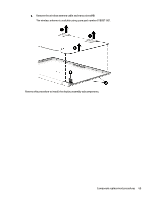
Disconnect the webcam/microphone module cable, from the webcam/microphone module.
 |
View all HP ENVY 14-j000 manuals
Add to My Manuals
Save this manual to your list of manuals |
Page 77 highlights
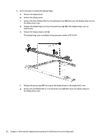
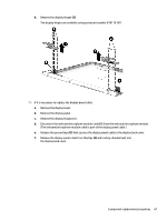
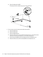
h. Remove the display hinges (3). The display hinges are available using spare part number 818119-001. 11. If it is necessary to replace the display panel cable: a. Remove the display bezel. b. Remove the display panel. c. Remove the display hingecover. d. Disconnect the webcam/microphone module cable (1) from the webcam/microphone module. (The webcam/microphone module cable is part of the display panel cable.) e. Release the ground tape (2) that secures the display panel cable to the display back cover. f. Release the display panel cable from theclips (3) and routing channel built into the display back cover. Component replacement procedures 67
-
 1
1 -
2
-
3
-
4
-
5
-
6
-
7
-
8
-
9
-
10
-
11
-
12
-
13
-
14
-
15
-
16
-
17
-
18
-
19
-
20
-
21
-
22
-
23
-
24
-
25
-
26
-
27
-
28
-
29
-
30
-
31
-
32
-
33
-
34
-
35
-
36
-
37
-
38
-
39
-
40
-
41
-
42
-
43
-
44
-
45
-
46
-
47
-
48
-
49
-
50
-
51
-
52
-
53
-
54
-
55
-
56
-
57
-
58
-
59
-
60
-
61
-
62
-
63
-
64
-
65
-
66
-
67
-
68
-
69
-
70
-
71
-
 72
72 -
 73
73 -
 74
74 -
 75
75 -
 76
76 -
 77
77 -
 78
78 -
 79
79 -
 80
80 -
 81
81 -
 82
82 -
83
-
84
-
85
-
86
-
87
-
88
-
89
-
90
-
91
-
92
-
93
-
94
-
95
-
96
-
97
-
98
-
99
-
100
-
101
-
102
-
103
-
104
 |
 |

h.
Remove the display hinges
(3)
.
The display hinges are available using spare part number 818119-001.
11.
If it is necessary to replace the display panel cable:
a.
Remove the display bezel.
b.
Remove the display panel.
c.
Remove the display hingecover.
d.
Disconnect the webcam/microphone module cable
(1)
from the webcam/microphone module.
(The webcam/microphone module cable is part of the display panel cable.)
e.
Release the ground tape
(2)
that secures the display panel cable to the display back cover.
f.
Release the display panel cable from theclips
(3)
and routing channel built into
the display back cover.
Component replacement procedures
67