HP ENVY 14-j000 ENVY Notebook model numbers used: 14-j000 through 14-j099 Main - Page 65
Heat sink, Battery see
 |
View all HP ENVY 14-j000 manuals
Add to My Manuals
Save this manual to your list of manuals |
Page 65 highlights
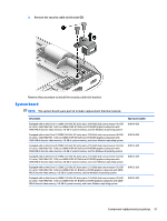
7. Remove the system board (2) by sliding it up and to the left at an angle. Reverse this procedure to install the system board. Heat sink NOTE: The heat sink spare part kit includes replacement thermal material. Description For use only on computer models equipped with a graphics subsystem with discrete memory For use only on computer models equipped with a graphics subsystem with UMA memory Spare part number 818112-001 818111-001 Before removing the heat sink, follow these steps: 1. Turn off the computer. If you are unsure whether the computer is off or in Hibernation, turn the computer on, and then shut it down through the operating system. 2. Disconnect the power from the computer by unplugging the power cord from the computer. 3. Disconnect all external devices from the computer. 4. Remove the bottom cover (see Bottom cover on page 27), and then remove the following components: a. Battery (see Battery on page 37) b. Fan (see Fan on page 46) c. RJ45 cover (see RJ45 cover on page 48) d. Security cable slot bracket (see Security cable slot bracket on page 50) e. System board (see System board on page 51) Remove the heat sink: Component replacement procedures 55
-
 1
1 -
2
-
3
-
4
-
5
-
6
-
7
-
8
-
9
-
10
-
11
-
12
-
13
-
14
-
15
-
16
-
17
-
18
-
19
-
20
-
21
-
22
-
23
-
24
-
25
-
26
-
27
-
28
-
29
-
30
-
31
-
32
-
33
-
34
-
35
-
36
-
37
-
38
-
39
-
40
-
41
-
42
-
43
-
44
-
45
-
46
-
47
-
48
-
49
-
50
-
51
-
52
-
53
-
54
-
55
-
56
-
57
-
58
-
59
-
 60
60 -
 61
61 -
 62
62 -
 63
63 -
 64
64 -
 65
65 -
 66
66 -
 67
67 -
 68
68 -
 69
69 -
 70
70 -
71
-
72
-
73
-
74
-
75
-
76
-
77
-
78
-
79
-
80
-
81
-
82
-
83
-
84
-
85
-
86
-
87
-
88
-
89
-
90
-
91
-
92
-
93
-
94
-
95
-
96
-
97
-
98
-
99
-
100
-
101
-
102
-
103
-
104
 |
 |
