HP ENVY 14-j000 ENVY Notebook model numbers used: 14-j000 through 14-j099 Main - Page 66
Steps 3 and 4 apply to computer models equipped with a graphics subsystem with UMA
 |
View all HP ENVY 14-j000 manuals
Add to My Manuals
Save this manual to your list of manuals |
Page 66 highlights
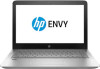
NOTE: Steps 1 and 2 apply to computer models equipped with a graphics subsystem with discrete memory. See steps 3 and 4 for heat sink removal steps for computer models equipped with a graphics subsystem with UMA memory. 1. Following the 1, 2, 3, 4, 5, 6, 7 sequence stamped into the heat sink, remove the seven Phillips PM2.0×3.3 screws (1) that secure the heat sink to the system board. 2. Remove the heat sink (2). NOTE: Due to the adhesive quality of the thermal material located between the heat sink and system board components, it may be necessary to move the heat sink from side to side to detach it. NOTE: Steps 3 and 4 apply to computer models equipped with a graphics subsystem with UMA memory. See steps 1 and 2 for heat sink removal steps for computer models equipped with a graphics subsystem with discrete memory. 3. Following the 1, 2, 3, 4 sequence stamped into the heat sink, remove the four Phillips PM2.0×3.3 screws (1) that secure the heat sink to the system board. 56 Chapter 6 Removal and replacement procedures for Authorized Service Provider parts
-
 1
1 -
2
-
3
-
4
-
5
-
6
-
7
-
8
-
9
-
10
-
11
-
12
-
13
-
14
-
15
-
16
-
17
-
18
-
19
-
20
-
21
-
22
-
23
-
24
-
25
-
26
-
27
-
28
-
29
-
30
-
31
-
32
-
33
-
34
-
35
-
36
-
37
-
38
-
39
-
40
-
41
-
42
-
43
-
44
-
45
-
46
-
47
-
48
-
49
-
50
-
51
-
52
-
53
-
54
-
55
-
56
-
57
-
58
-
59
-
60
-
 61
61 -
 62
62 -
 63
63 -
 64
64 -
 65
65 -
 66
66 -
 67
67 -
 68
68 -
 69
69 -
 70
70 -
 71
71 -
72
-
73
-
74
-
75
-
76
-
77
-
78
-
79
-
80
-
81
-
82
-
83
-
84
-
85
-
86
-
87
-
88
-
89
-
90
-
91
-
92
-
93
-
94
-
95
-
96
-
97
-
98
-
99
-
100
-
101
-
102
-
103
-
104
 |
 |
