HP EliteBook 800 EliteBook 820 G4 Notebook PC EliteBook 828 G4 Notebook PC Mai - Page 16
Left
 |
View all HP EliteBook 800 manuals
Add to My Manuals
Save this manual to your list of manuals |
Page 16 highlights
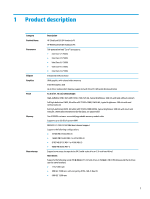
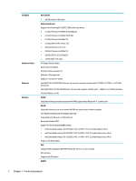
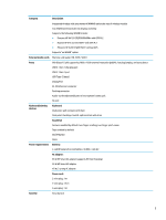
Component (5) USB 3.x port (6) RJ-45 (network) jack/status lights (7) Docking connector (8) SIM card slot (9) Power connector Left Description ▲ Press in on the card, and then remove it from the memory card reader. Connects a USB device, such as a cell phone, camera, activity tracker, or smartwatch, and provides data transfer. Connects a network cable. ● Green (left): The network is connected. ● Amber (right): Activity is occurring on the network. Connects an optional docking device. Supports a wireless subscriber identity module (SIM) card. Connects an AC adapter. Component (1) Security cable slot (2) Vents (2) (3) External monitor port (4) USB 3.x charging port (5) Smart card reader 6 Chapter 2 External component identification Description Attaches an optional security cable to the computer. NOTE: The security cable is designed to act as a deterrent, but it may not prevent the computer from being mishandled or stolen. Enable airflow to cool internal components. NOTE: The computer fan starts up automatically to cool internal components and prevent overheating. It is normal for the internal fan to cycle on and off during routine operation. Connects an external VGA monitor or projector. When the computer is on, connects and charges a USB device, such as a cell phone, camera, activity tracker, or smartwatch, and provides high-speed data transfer. Supports optional smart cards.
-
 1
1 -
2
-
3
-
4
-
5
-
6
-
7
-
8
-
9
-
10
-
 11
11 -
 12
12 -
 13
13 -
 14
14 -
 15
15 -
 16
16 -
 17
17 -
 18
18 -
 19
19 -
 20
20 -
 21
21 -
22
-
23
-
24
-
25
-
26
-
27
-
28
-
29
-
30
-
31
-
32
-
33
-
34
-
35
-
36
-
37
-
38
-
39
-
40
-
41
-
42
-
43
-
44
-
45
-
46
-
47
-
48
-
49
-
50
-
51
-
52
-
53
-
54
-
55
-
56
-
57
-
58
-
59
-
60
-
61
-
62
-
63
-
64
-
65
-
66
-
67
-
68
-
69
-
70
-
71
-
72
-
73
-
74
-
75
-
76
-
77
-
78
-
79
-
80
-
81
-
82
-
83
-
84
-
85
-
86
-
87
-
88
-
89
-
90
-
91
-
92
-
93
-
94
-
95
-
96
-
97
-
98
-
99
-
100
-
101
-
102
-
103
-
104
-
105
 |
 |
