HP Envy 15-1000se HP ENVY 15 - Maintenance and Service Guide - Page 49
from the low insertion force LIF connector on the system board., Disconnect the TouchPad cable
 |
View all HP Envy 15-1000se manuals
Add to My Manuals
Save this manual to your list of manuals |
Page 49 highlights
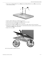
Removal and replacement procedures 2. Remove the two Phillips PM2.0×5.0 screws 1 and the four Phillips PM2.0×2.0 screws 2 that secure the top cover to the base enclosure. 3. Turn the computer right-side up, with the front toward you. 4. Release the top cover by lifting the front edge 1 until it rests at an angle. 5. Disconnect the LED board cable 2 from the system board. 6. Disconnect the TouchPad cable 3 from the low insertion force (LIF) connector on the system board. 7. Release the zero insertion force (ZIF) connector to which the keyboard cable is attached, and then disconnect the keyboard cable 4 from the system board. 8. Remove the top cover 5. Reverse this procedure to install the top cover. Maintenance and Service Guide 4-11
-
 1
1 -
2
-
3
-
4
-
5
-
6
-
7
-
8
-
9
-
10
-
11
-
12
-
13
-
14
-
15
-
16
-
17
-
18
-
19
-
20
-
21
-
22
-
23
-
24
-
25
-
26
-
27
-
28
-
29
-
30
-
31
-
32
-
33
-
34
-
35
-
36
-
37
-
38
-
39
-
40
-
41
-
42
-
43
-
 44
44 -
 45
45 -
 46
46 -
 47
47 -
 48
48 -
 49
49 -
 50
50 -
 51
51 -
 52
52 -
 53
53 -
 54
54 -
55
-
56
-
57
-
58
-
59
-
60
-
61
-
62
-
63
-
64
-
65
-
66
-
67
-
68
-
69
-
70
-
71
-
72
-
73
-
74
-
75
-
76
-
77
-
78
-
79
-
80
-
81
-
82
-
83
-
84
-
85
-
86
-
87
-
88
-
89
-
90
-
91
-
92
-
93
-
94
-
95
-
96
-
97
-
98
-
99
-
100
-
101
-
102
-
103
-
104
-
105
-
106
-
107
-
108
-
109
-
110
-
111
-
112
-
113
-
114
-
115
-
116
-
117
-
118
-
119
-
120
-
121
-
122
-
123
-
124
-
125
-
126
-
127
-
128
-
129
-
130
-
131
 |
 |

Removal and replacement procedures
Maintenance and Service Guide
4–11
2. Remove the two Phillips PM2.0×5.0 screws
1
and the four Phillips PM2.0×2.0 screws
2
that secure the top
cover to the base enclosure.
3. Turn the computer right-side up, with the front toward you.
4. Release the top cover by lifting the front edge
1
until it rests at an angle.
5. Disconnect the LED board cable
2
from the system board.
6. Disconnect the TouchPad cable
3
from the low insertion force (LIF) connector on the system board.
7. Release the zero insertion force (ZIF) connector to which the keyboard cable is attached, and then disconnect
the keyboard cable
4
from the system board.
8. Remove the top cover
5
.
Reverse this procedure to install the top cover.