HP Envy 15-1000se HP ENVY 15 - Maintenance and Service Guide - Page 60
Processor fan/heat sink assembly
 |
View all HP Envy 15-1000se manuals
Add to My Manuals
Save this manual to your list of manuals |
Page 60 highlights
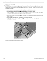
Removal and replacement procedures Processor fan/heat sink assembly Description Processor fan/heat sink assembly (includes replacement thermal material) Spare part number 576837-001 Before removing the processor fan/heat sink assembly, follow these steps: 1. Shut down the computer. 2. Disconnect all external devices connected to the computer. 3. Disconnect the power from the computer by first unplugging the power cord from the AC outlet, and then unplugging the AC adapter from the computer. 4. Remove the battery (see "Battery" on page 4-7). 5. Remove the memory module compartment cover (see "Expansion memory module" on page 4-8). 6. Remove the top cover (see "Top cover" on page 4-10). Remove the processor fan/heat sink assembly: 1. Disconnect the fan cable 1 from the system board. 2. Following the 1, 2, 3, 4 sequence stamped into the processor fan/heat sink assembly, loosen the four Phillips PM2.0×6.0 captive screws 2 that secure the processor fan/heat sink assembly to the system board. 3. Remove the Phillips PM2.0×3.0 screw 3 that secures the processor fan/heat sink assembly to the system board. 4. Remove the processor fan/heat sink assembly 4. ✎ Due to the adhesive quality of the thermal material located between the processor fan/heat sink assembly and system board components, it may be necessary to move the processor fan/heat sink assembly from side to side to detach it. 4-22 Maintenance and Service Guide
-
 1
1 -
2
-
3
-
4
-
5
-
6
-
7
-
8
-
9
-
10
-
11
-
12
-
13
-
14
-
15
-
16
-
17
-
18
-
19
-
20
-
21
-
22
-
23
-
24
-
25
-
26
-
27
-
28
-
29
-
30
-
31
-
32
-
33
-
34
-
35
-
36
-
37
-
38
-
39
-
40
-
41
-
42
-
43
-
44
-
45
-
46
-
47
-
48
-
49
-
50
-
51
-
52
-
53
-
54
-
 55
55 -
 56
56 -
 57
57 -
 58
58 -
 59
59 -
 60
60 -
 61
61 -
 62
62 -
 63
63 -
 64
64 -
 65
65 -
66
-
67
-
68
-
69
-
70
-
71
-
72
-
73
-
74
-
75
-
76
-
77
-
78
-
79
-
80
-
81
-
82
-
83
-
84
-
85
-
86
-
87
-
88
-
89
-
90
-
91
-
92
-
93
-
94
-
95
-
96
-
97
-
98
-
99
-
100
-
101
-
102
-
103
-
104
-
105
-
106
-
107
-
108
-
109
-
110
-
111
-
112
-
113
-
114
-
115
-
116
-
117
-
118
-
119
-
120
-
121
-
122
-
123
-
124
-
125
-
126
-
127
-
128
-
129
-
130
-
131
 |
 |
