HP LaserJet 5L Service Manual - Page 60
Control Panel, Resolution Enhancement REt
 |
View all HP LaserJet 5L manuals
Add to My Manuals
Save this manual to your list of manuals |
Page 60 highlights
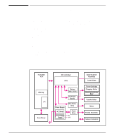
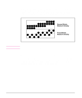
Control Panel Status LED Lights The Formatter uses three LEDs mounted under the printer cover to communicate printer status to the user. Refer to "Using the Control Panel" in Chapter 3 and "Printer Error Troubleshooting" in Chapter 7 for more information on the lights. Front Panel Button The Formatter PCA is connected to a microswitch located on the control panel PCA. The single button is used for such functions as self test, reset, and to display error codes. Refer to "Using the Control Panel" in Chapter 3 for more information on the Front Panel Button. Resolution Enhancement (REt) The Formatter PCA contains circuitry for Resolution Enhancement technology (REt), which modifies the standard video dot data on its way to the DC Controller to produce "smoothed" black-to-white boundaries. REt is user-adjustable from some software applications. Available settings are On or Off. Functional Overview 5 - 9 Functional 5 Overview
-
 1
1 -
2
-
3
-
4
-
5
-
6
-
7
-
8
-
9
-
10
-
11
-
12
-
13
-
14
-
15
-
16
-
17
-
18
-
19
-
20
-
21
-
22
-
23
-
24
-
25
-
26
-
27
-
28
-
29
-
30
-
31
-
32
-
33
-
34
-
35
-
36
-
37
-
38
-
39
-
40
-
41
-
42
-
43
-
44
-
45
-
46
-
47
-
48
-
49
-
50
-
51
-
52
-
53
-
54
-
 55
55 -
 56
56 -
 57
57 -
 58
58 -
 59
59 -
 60
60 -
 61
61 -
 62
62 -
 63
63 -
 64
64 -
 65
65 -
66
-
67
-
68
-
69
-
70
-
71
-
72
-
73
-
74
-
75
-
76
-
77
-
78
-
79
-
80
-
81
-
82
-
83
-
84
-
85
-
86
-
87
-
88
-
89
-
90
-
91
-
92
-
93
-
94
-
95
-
96
-
97
-
98
-
99
-
100
-
101
-
102
-
103
-
104
-
105
-
106
-
107
-
108
-
109
-
110
-
111
-
112
-
113
-
114
-
115
-
116
-
117
-
118
-
119
-
120
-
121
-
122
-
123
-
124
-
125
-
126
-
127
-
128
-
129
-
130
-
131
-
132
-
133
-
134
-
135
-
136
-
137
-
138
-
139
-
140
-
141
-
142
-
143
-
144
-
145
-
146
-
147
-
148
-
149
-
150
-
151
-
152
-
153
-
154
-
155
-
156
-
157
-
158
-
159
-
160
-
161
-
162
-
163
-
164
-
165
-
166
-
167
-
168
-
169
-
170
-
171
-
172
-
173
-
174
-
175
-
176
-
177
-
178
-
179
-
180
-
181
-
182
-
183
-
184
-
185
-
186
-
187
-
188
-
189
-
190
-
191
-
192
-
193
-
194
-
195
-
196
-
197
-
198
-
199
-
200
-
201
-
202
-
203
-
204
 |
 |
