HP LaserJet 5L Service Manual - Page 64
Toner Cartridge, Step 1: Drum Cleaning, Step 2: Drum Conditioning, Step 3: Image Writing
 |
View all HP LaserJet 5L manuals
Add to My Manuals
Save this manual to your list of manuals |
Page 64 highlights
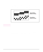
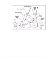
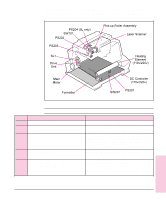
CAUTION Toner Cartridge As the "heart" of the Image Formation System, the toner cartridge houses the cleaning, conditioning, and developing steps of the process. The toner cartridge contains the photosensitive drum, primary charging roller, developing station, toner cavity, and cleaning station. Including these components, which wear, degrade, or are consumed in the replaceable toner cartridge, eliminates the need for a service call when replacement is required. The special photosensitive properties of the drum allow an image to be formed on the drum surface and then transferred to paper. The printer's toner cartridge does not include a light-blocking shutter. Be careful to avoid exposing the drum to light, which can permanently damage the drum. Protect the cartridge whenever removing it from the printer. Step 1: Drum Cleaning The cleaning blade is in contact with the surface of the drum at all times. As the drum rotates during printing, excess toner wiped off and stored in the waste toner receptacle. Step 2: Drum Conditioning After the drum is physically cleaned, it must be conditioned. This process consists of applying a uniform negative charge on the surface of the drum with the primary charging roller, located in the toner cartridge. The primary charging roller is coated with conductive rubber. An AC bias is applied to the roller to erase any residual charges from any previous image. In addition, a negative DC bias is applied by the charging roller to create a uniform negative potential on the drum surface. The amount of DC voltage is modified by the print density setting. Step 3: Image Writing During the writing process, a modulated laser diode projects the beam onto a rotating scanning mirror. As the mirror rotates, the beam reflects off the mirror, first through a set of focusing lenses, off a mirror, and finally through a slot in the top of the toner cartridge, and onto the photosensitive drum. The beam sweeps the drum from left to right, discharging the negative potential wherever the beam strikes the surface. This creates a latent electrostatic image, which later is developed into a visible image. Because the beam is sweeping the entire length of the drum and the drum is rotating, the entire surface area of the drum can be covered. At the end of each sweep, the beam strikes the beam detect lens, generating the Beam Detect Signal (BD). The BD signal is sent to the DC Controller, where it is converted to an electrical signal used to synchronize the output of the next scan line of data. Functional Overview 5 - 13 Functional 5 Overview
-
 1
1 -
2
-
3
-
4
-
5
-
6
-
7
-
8
-
9
-
10
-
11
-
12
-
13
-
14
-
15
-
16
-
17
-
18
-
19
-
20
-
21
-
22
-
23
-
24
-
25
-
26
-
27
-
28
-
29
-
30
-
31
-
32
-
33
-
34
-
35
-
36
-
37
-
38
-
39
-
40
-
41
-
42
-
43
-
44
-
45
-
46
-
47
-
48
-
49
-
50
-
51
-
52
-
53
-
54
-
55
-
56
-
57
-
58
-
 59
59 -
 60
60 -
 61
61 -
 62
62 -
 63
63 -
 64
64 -
 65
65 -
 66
66 -
 67
67 -
 68
68 -
 69
69 -
70
-
71
-
72
-
73
-
74
-
75
-
76
-
77
-
78
-
79
-
80
-
81
-
82
-
83
-
84
-
85
-
86
-
87
-
88
-
89
-
90
-
91
-
92
-
93
-
94
-
95
-
96
-
97
-
98
-
99
-
100
-
101
-
102
-
103
-
104
-
105
-
106
-
107
-
108
-
109
-
110
-
111
-
112
-
113
-
114
-
115
-
116
-
117
-
118
-
119
-
120
-
121
-
122
-
123
-
124
-
125
-
126
-
127
-
128
-
129
-
130
-
131
-
132
-
133
-
134
-
135
-
136
-
137
-
138
-
139
-
140
-
141
-
142
-
143
-
144
-
145
-
146
-
147
-
148
-
149
-
150
-
151
-
152
-
153
-
154
-
155
-
156
-
157
-
158
-
159
-
160
-
161
-
162
-
163
-
164
-
165
-
166
-
167
-
168
-
169
-
170
-
171
-
172
-
173
-
174
-
175
-
176
-
177
-
178
-
179
-
180
-
181
-
182
-
183
-
184
-
185
-
186
-
187
-
188
-
189
-
190
-
191
-
192
-
193
-
194
-
195
-
196
-
197
-
198
-
199
-
200
-
201
-
202
-
203
-
204
 |
 |
