HP LaserJet 5L Service Manual - Page 66
Paper Feed System
 |
View all HP LaserJet 5L manuals
Add to My Manuals
Save this manual to your list of manuals |
Page 66 highlights
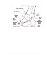
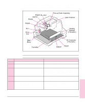
Paper Feed System Both the Paper Input Bin and the Single Sheet Input Slot merge into one, main input area. Paper placed in either of these areas enables the Paper Out Sensor (sensor 202), which informs the DC Controller that paper is present. When the printer receives a print job and is ready to print, the DC Controller enables the Laser/Scanner Assembly and the Motor. Paper motion begins when the DC Controller energizes solenoid SL1. This causes the paper pick up roller to rotate once. Two actions occur as a result of this rotation. First, the paper kick plate pushes the paper against the pick-up roller. Second, the pick-up roller grabs the top sheet and advances it to the Feed Assembly drive rollers. To ensure that only one sheet is fed, a main separation pad, along with two subpads, hold the remainder of the stack in place. The feed assembly drive rollers advance the paper to the Paper Registration photosensor (PS203). This sensor informs the DC Controller of the exact location of the paper's leading edge, so that the image being written on the photosensitive drum can be precisely positioned on the page. The feed assembly drive rollers then advance the paper to the transfer area where the toner image on the photosensitive drum is transferred to paper. After the image is transferred, the paper enters the fusing assembly where heat from the fuser and pressure from the Pressure Roller permanently bond the toner image to paper. The Paper Exit Sensor (PS201) determines that paper has successfully moved out of the fusing area. The fusing assembly exit rollers deliver paper to either the Output Paper Bin or the Front Output slot, depending upon the position of the Face-up/Face-down lever. Functional Overview 5 - 15 Functional 5 Overview
-
 1
1 -
2
-
3
-
4
-
5
-
6
-
7
-
8
-
9
-
10
-
11
-
12
-
13
-
14
-
15
-
16
-
17
-
18
-
19
-
20
-
21
-
22
-
23
-
24
-
25
-
26
-
27
-
28
-
29
-
30
-
31
-
32
-
33
-
34
-
35
-
36
-
37
-
38
-
39
-
40
-
41
-
42
-
43
-
44
-
45
-
46
-
47
-
48
-
49
-
50
-
51
-
52
-
53
-
54
-
55
-
56
-
57
-
58
-
59
-
60
-
 61
61 -
 62
62 -
 63
63 -
 64
64 -
 65
65 -
 66
66 -
 67
67 -
 68
68 -
 69
69 -
 70
70 -
 71
71 -
72
-
73
-
74
-
75
-
76
-
77
-
78
-
79
-
80
-
81
-
82
-
83
-
84
-
85
-
86
-
87
-
88
-
89
-
90
-
91
-
92
-
93
-
94
-
95
-
96
-
97
-
98
-
99
-
100
-
101
-
102
-
103
-
104
-
105
-
106
-
107
-
108
-
109
-
110
-
111
-
112
-
113
-
114
-
115
-
116
-
117
-
118
-
119
-
120
-
121
-
122
-
123
-
124
-
125
-
126
-
127
-
128
-
129
-
130
-
131
-
132
-
133
-
134
-
135
-
136
-
137
-
138
-
139
-
140
-
141
-
142
-
143
-
144
-
145
-
146
-
147
-
148
-
149
-
150
-
151
-
152
-
153
-
154
-
155
-
156
-
157
-
158
-
159
-
160
-
161
-
162
-
163
-
164
-
165
-
166
-
167
-
168
-
169
-
170
-
171
-
172
-
173
-
174
-
175
-
176
-
177
-
178
-
179
-
180
-
181
-
182
-
183
-
184
-
185
-
186
-
187
-
188
-
189
-
190
-
191
-
192
-
193
-
194
-
195
-
196
-
197
-
198
-
199
-
200
-
201
-
202
-
203
-
204
 |
 |
