HP Pavilion 11-s000 Maintenance and Service Guide - Page 32
Removal and replacement procedures, Keyboard/top cover
 |
View all HP Pavilion 11-s000 manuals
Add to My Manuals
Save this manual to your list of manuals |
Page 32 highlights
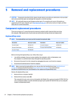
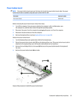
5 Removal and replacement procedures CAUTION: Components described in this chapter should only be accessed by an authorized service provider. Users who access these parts can damage the computer or void the warranty. NOTE: HP continually improves and changes product parts. For complete and current information on supported parts for your computer, go to http://partsurfer.hp.com, select your country or region, and then follow the on-screen instructions. Component replacement procedures There are as many as 57 screws that must be removed, replaced, and/or loosened when servicing the computer. Make special note of each screw size and location during removal and replacement. Keyboard/top cover NOTE: The keyboard/top cover spare part kit includes the keyboard cable. Description For use in Japan For use in South Korea For use in Taiwan Spare part number 837608-291 837608-AD1 837608-AB1 Description For use in Thailand For use in the United States Spare part number 837608-281 837608-001 Before removing the keyboard/top cover, follow these steps: 1. Turn off the computer. If you are unsure whether the computer is off or in Hibernation, turn the computer on, and then shut it down through the operating system. 2. Disconnect the power from the computer by unplugging the power cord from the computer. 3. Disconnect all external devices from the computer. NOTE: When replacing the keyboard/top cover, be sure that the TouchPad board (see TouchPad board on page 28) and power button board (see Power button board on page 29) are removed from the defective keyboard/top cover and installed on the replacement keyboard/top cover. Remove the keyboard/top cover: 1. Remove the four computer feet (1). 2. Remove the two screw covers (2). The computer feet and screw covers are included in the Rubber Kits, spare part number 837603-001 (for use on computer models in sunset red finish) and spare part number 837604-001 (for use on computer models in twinkle black finish). 24 Chapter 5 Removal and replacement procedures
-
 1
1 -
2
-
3
-
4
-
5
-
6
-
7
-
8
-
9
-
10
-
11
-
12
-
13
-
14
-
15
-
16
-
17
-
18
-
19
-
20
-
21
-
22
-
23
-
24
-
25
-
26
-
 27
27 -
 28
28 -
 29
29 -
 30
30 -
 31
31 -
 32
32 -
 33
33 -
 34
34 -
 35
35 -
 36
36 -
 37
37 -
38
-
39
-
40
-
41
-
42
-
43
-
44
-
45
-
46
-
47
-
48
-
49
-
50
-
51
-
52
-
53
-
54
-
55
-
56
-
57
-
58
-
59
-
60
-
61
-
62
-
63
-
64
-
65
-
66
-
67
-
68
-
69
-
70
-
71
-
72
-
73
-
74
 |
 |
