HP Pavilion 11-s000 Maintenance and Service Guide - Page 49
that secure the system board to the bottom cover., Remove the four Philllips PM2.0×3.3 screws
 |
View all HP Pavilion 11-s000 manuals
Add to My Manuals
Save this manual to your list of manuals |
Page 49 highlights
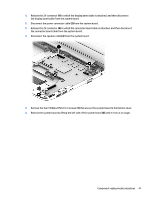
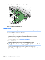
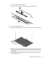
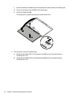
1. Release the ZIF connector (1) to which the display panel cable is attached, and then disconnect the display panel cable from the system board. 2. Disconnect the power connector cable (2) from the system board. 3. Release the ZIF connector (3) to which the connector board cable is attached, and then disconnect the connector board cable from the system board. 4. Disconnect the speaker cable (4) from the system board. 5. Remove the four Philllips PM2.0×3.3 screws (1) that secure the system board to the bottom cover. 6. Release the system board by lifting the left side of the system board (2) until it rests at an angle. Component replacement procedures 41
-
 1
1 -
2
-
3
-
4
-
5
-
6
-
7
-
8
-
9
-
10
-
11
-
12
-
13
-
14
-
15
-
16
-
17
-
18
-
19
-
20
-
21
-
22
-
23
-
24
-
25
-
26
-
27
-
28
-
29
-
30
-
31
-
32
-
33
-
34
-
35
-
36
-
37
-
38
-
39
-
40
-
41
-
42
-
43
-
 44
44 -
 45
45 -
 46
46 -
 47
47 -
 48
48 -
 49
49 -
 50
50 -
 51
51 -
 52
52 -
 53
53 -
 54
54 -
55
-
56
-
57
-
58
-
59
-
60
-
61
-
62
-
63
-
64
-
65
-
66
-
67
-
68
-
69
-
70
-
71
-
72
-
73
-
74
 |
 |

1.
Release the ZIF connector
(1)
to which the display panel cable is attached, and then disconnect
the display panel cable from the system board.
2.
Disconnect the power connector cable
(2)
from the system board.
3.
Release the ZIF connector
(3)
to which the connector board cable is attached, and then disconnect
the connector board cable from the system board.
4.
Disconnect the speaker cable
(4)
from the system board.
5.
Remove the four Philllips PM2.0×3.3 screws
(1)
that secure the system board to the bottom cover.
6.
Release the system board by lifting the left side of the system board
(2)
until it rests at an angle.
Component replacement procedures
41