HP Pavilion TouchSmart 11-e140ca HP 210 G1 Notebook PC HP Pavilion 11 Notebook - Page 63
Display assembly, HP 215 G1 Notebook PC non-touchscreen
 |
View all HP Pavilion TouchSmart 11-e140ca manuals
Add to My Manuals
Save this manual to your list of manuals |
Page 63 highlights
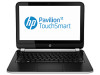
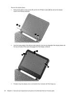
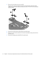
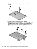
Display assembly NOTE: HP 210 G1 Notebook PC touchscreen, HP Pavilion TouchSmart 11 Notebook, HP Pavilion 11 Notebook touchscreen, and HP 215 G1 Notebook PC touchscreen computer models are spared at the display assembly only. The display assemblies for the HP 210 G1 Notebook PC non-touchscreen, HP 215 G1 Notebook PC non-touchscreen, and for HP Pavilion 11 Notebooks non-touchscreen computer models are spared at the subcomponent-level only. For procedures to replace the display assembly subcomponents for those non-touchscreen models, see Display assembly subcomponents on page 56. Description 11.6 inch (29.46 cm), SVA, LED touchscreen display assembly (includes webcam/microphone module and wireless antenna cables), for use with HP 210 G1 touchscreen computer models 11.6 inch (29.46 cm), SVA, LED touchscreen display assembly (includes webcam/microphone module and wireless antenna cables), for use with HP Pavilion TouchSmart 11 Notebook, HP Pavilion 11 Notebook touchscreen, or HP 215 G1 Notebook PC touchscreen computer models Spare part number 755303-001 753948-001 Before removing the display assembly, follow these steps: 1. Turn off the computer. If you are unsure whether the computer is off or in Hibernation, turn the computer on, and then shut it down through the operating system. 2. Disconnect the power from the computer by unplugging the power cord from the computer. 3. Disconnect all external devices from the computer. 4. Remove the battery (see Battery on page 40). 5. Remove the service door (see Service door on page 41). Remove the display assembly: 1. Remove the rear rubber feet (1). The rear rubber feet are included in the Rubber Feet Kit, spare part number 730888-001. 2. Remove the two Phillips PM2.2×5.5 screws (2) that secure the rear corner covers to the computer. Component replacement procedures 53
-
 1
1 -
2
-
3
-
4
-
5
-
6
-
7
-
8
-
9
-
10
-
11
-
12
-
13
-
14
-
15
-
16
-
17
-
18
-
19
-
20
-
21
-
22
-
23
-
24
-
25
-
26
-
27
-
28
-
29
-
30
-
31
-
32
-
33
-
34
-
35
-
36
-
37
-
38
-
39
-
40
-
41
-
42
-
43
-
44
-
45
-
46
-
47
-
48
-
49
-
50
-
51
-
52
-
53
-
54
-
55
-
56
-
57
-
 58
58 -
 59
59 -
 60
60 -
 61
61 -
 62
62 -
 63
63 -
 64
64 -
 65
65 -
 66
66 -
 67
67 -
 68
68 -
69
-
70
-
71
-
72
-
73
-
74
-
75
-
76
-
77
-
78
-
79
-
80
-
81
-
82
-
83
-
84
-
85
-
86
-
87
-
88
-
89
-
90
-
91
-
92
-
93
-
94
-
95
-
96
-
97
-
98
-
99
-
100
-
101
-
102
-
103
-
104
-
105
-
106
-
107
-
108
-
109
-
110
-
111
 |
 |