HP Pavilion TouchSmart 11-e140ca HP 210 G1 Notebook PC HP Pavilion 11 Notebook - Page 84
detach it., the system board components
 |
View all HP Pavilion TouchSmart 11-e140ca manuals
Add to My Manuals
Save this manual to your list of manuals |
Page 84 highlights
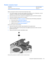
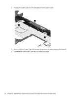
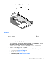
e. Media card reader board (see Media card reader board on page 67) f. Fan (see Fan on page 68) g. System board (see System board on page 70) Remove the heat sink: 1. Turn the system board upside down, with the front toward you. 2. Following the 1 through 4 sequence stamped into the heat sink, loosen the four captive Phillips PM2.0×2.5 screws (1) that secure the heat sink to the system board. 3. Remove the heat sink (2). NOTE: Due to the adhesive quality of the thermal material located between the heat sink and the system board components, it may be necessary to move the heat sink from side to side to detach it. NOTE: The thermal material must be thoroughly cleaned from the surfaces of the heat sink and the system board components each time the heat sink is removed. Thermal paste is used on the processor (1) and the heat sink section (2) that services it 74 Chapter 6 Removal and replacement procedures for Authorized Service Provider parts
-
 1
1 -
2
-
3
-
4
-
5
-
6
-
7
-
8
-
9
-
10
-
11
-
12
-
13
-
14
-
15
-
16
-
17
-
18
-
19
-
20
-
21
-
22
-
23
-
24
-
25
-
26
-
27
-
28
-
29
-
30
-
31
-
32
-
33
-
34
-
35
-
36
-
37
-
38
-
39
-
40
-
41
-
42
-
43
-
44
-
45
-
46
-
47
-
48
-
49
-
50
-
51
-
52
-
53
-
54
-
55
-
56
-
57
-
58
-
59
-
60
-
61
-
62
-
63
-
64
-
65
-
66
-
67
-
68
-
69
-
70
-
71
-
72
-
73
-
74
-
75
-
76
-
77
-
78
-
 79
79 -
 80
80 -
 81
81 -
 82
82 -
 83
83 -
 84
84 -
 85
85 -
 86
86 -
 87
87 -
 88
88 -
 89
89 -
90
-
91
-
92
-
93
-
94
-
95
-
96
-
97
-
98
-
99
-
100
-
101
-
102
-
103
-
104
-
105
-
106
-
107
-
108
-
109
-
110
-
111
 |
 |