HP Pavilion TouchSmart 11-e140ca HP 210 G1 Notebook PC HP Pavilion 11 Notebook - Page 71
Bottom cover, Release the zero insertion force ZIF connector
 |
View all HP Pavilion TouchSmart 11-e140ca manuals
Add to My Manuals
Save this manual to your list of manuals |
Page 71 highlights
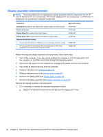
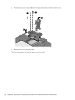
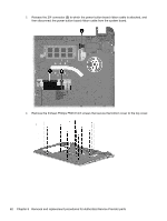
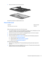
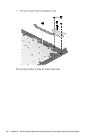
Bottom cover Description Touchscreen models (includes left and right corner covers) Non-touchscreen computer models (includes left and right corner covers) Spare part number 730887-001 747750-001 Before removing the bottom cover, follow these steps: 1. Turn off the computer. If you are unsure whether the computer is off or in Hibernation, turn the computer on, and then shut it down through the operating system. 2. Disconnect the power from the computer by unplugging the power cord from the computer. 3. Disconnect all external devices from the computer. 4. Remove the battery (see Battery on page 40). 5. Remove the service door (see Service door on page 41). 6. Disconnect the RTC battery cable from the system board (see RTC battery on page 47). 7. Remove the display assembly (see Display assembly on page 53). NOTE: When replacing the bottom cover, be sure that the RTC battery is removed from the defective bottom cover and installed in the replacement bottom cover. Remove the bottom cover: 1. Release the zero insertion force (ZIF) connector (1) to which the keyboard cable is attached, and then disconnect the keyboard cable from the system board. 2. Release the ZIF connector (2) to which the TouchPad button board cable is attached, and then disconnect the TouchPad button board cable from the system board. Component replacement procedures 61
-
 1
1 -
2
-
3
-
4
-
5
-
6
-
7
-
8
-
9
-
10
-
11
-
12
-
13
-
14
-
15
-
16
-
17
-
18
-
19
-
20
-
21
-
22
-
23
-
24
-
25
-
26
-
27
-
28
-
29
-
30
-
31
-
32
-
33
-
34
-
35
-
36
-
37
-
38
-
39
-
40
-
41
-
42
-
43
-
44
-
45
-
46
-
47
-
48
-
49
-
50
-
51
-
52
-
53
-
54
-
55
-
56
-
57
-
58
-
59
-
60
-
61
-
62
-
63
-
64
-
65
-
 66
66 -
 67
67 -
 68
68 -
 69
69 -
 70
70 -
 71
71 -
 72
72 -
 73
73 -
 74
74 -
 75
75 -
 76
76 -
77
-
78
-
79
-
80
-
81
-
82
-
83
-
84
-
85
-
86
-
87
-
88
-
89
-
90
-
91
-
92
-
93
-
94
-
95
-
96
-
97
-
98
-
99
-
100
-
101
-
102
-
103
-
104
-
105
-
106
-
107
-
108
-
109
-
110
-
111
 |
 |