HP Pavilion TouchSmart 11-e140ca HP 210 G1 Notebook PC HP Pavilion 11 Notebook - Page 79
Monitor connector board
 |
View all HP Pavilion TouchSmart 11-e140ca manuals
Add to My Manuals
Save this manual to your list of manuals |
Page 79 highlights
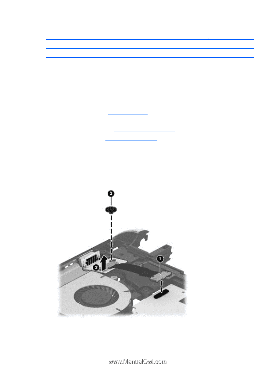
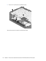
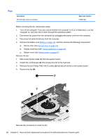
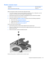
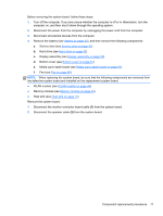
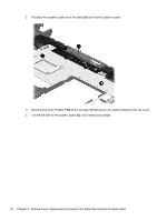
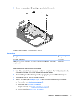
Monitor connector board Description Monitor connector board (includes cable) Spare part number 730901-001 Before removing the monitor connector board, follow these steps: 1. Turn off the computer. If you are unsure whether the computer is off or in Hibernation, turn the computer on, and then shut it down through the operating system. 2. Disconnect the power from the computer by unplugging the power cord from the computer. 3. Disconnect all external devices from the computer. 4. Remove the battery (see Battery on page 40), and then remove the following components: a. Service door (see Service door on page 41) b. Display assembly (see Display assembly on page 53) c. Bottom cover (see Bottom cover on page 61) Remove the monitor connector board: 1. Disconnect the monitor connector board cable (1) from the system board. 2. Remove the Phillips PM2.0×2.25 broad head screw (2) that secures the monitor connector board to the top cover. 3. Remove the monitor connector board (3) and cable. Reverse this procedure to install the monitor connector board. Component replacement procedures 69
-
 1
1 -
2
-
3
-
4
-
5
-
6
-
7
-
8
-
9
-
10
-
11
-
12
-
13
-
14
-
15
-
16
-
17
-
18
-
19
-
20
-
21
-
22
-
23
-
24
-
25
-
26
-
27
-
28
-
29
-
30
-
31
-
32
-
33
-
34
-
35
-
36
-
37
-
38
-
39
-
40
-
41
-
42
-
43
-
44
-
45
-
46
-
47
-
48
-
49
-
50
-
51
-
52
-
53
-
54
-
55
-
56
-
57
-
58
-
59
-
60
-
61
-
62
-
63
-
64
-
65
-
66
-
67
-
68
-
69
-
70
-
71
-
72
-
73
-
 74
74 -
 75
75 -
 76
76 -
 77
77 -
 78
78 -
 79
79 -
 80
80 -
 81
81 -
 82
82 -
 83
83 -
 84
84 -
85
-
86
-
87
-
88
-
89
-
90
-
91
-
92
-
93
-
94
-
95
-
96
-
97
-
98
-
99
-
100
-
101
-
102
-
103
-
104
-
105
-
106
-
107
-
108
-
109
-
110
-
111
 |
 |