HP Pavilion dv6-2100 HP Pavilion dv6 Entertainment PC - Maintenance and Servic - Page 64
Display assembly, Remove the WLAN antenna cables and the microphone cable from the clips
 |
View all HP Pavilion dv6-2100 manuals
Add to My Manuals
Save this manual to your list of manuals |
Page 64 highlights
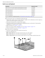
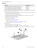
Display assembly Removal and replacement procedures Description 15.6-inch WXGA BrightView display assembly for use in white computers (includes webcam, 2 microphones, and 2 wireless antenna transceivers and cables) 15.6-inch WXGA BrightView display assembly for use in black computers (includes webcam, 2 microphones, and 2 wireless antenna transceivers and cables) Spare part number 578257-001 578256-001 Before removing the display assembly, follow these steps: 1. Shut down the computer. If you are unsure whether the computer is off or in Hibernation, turn the computer on, and then shut it down through the operating system. 2. Disconnect all external devices connected to the computer. 3. Disconnect the power from the computer by first unplugging the power cord from the AC outlet and then unplugging the AC adapter from the computer. 4. Remove the battery (see "Battery" on page 4-7). 5. Remove the following components: a. Disconnect the wireless antenna cables from the WLAN module (see "WLAN module" on page 4-17). b. Switch cover and keyboard (see "Switch cover and keyboard" on page 4-20). Remove the display assembly: 1. Disconnect the display panel cable 1 from the system board. 2. Remove the WLAN antenna cables and the microphone cable from the clips 2 built into the top cover. 3. Disconnect the webcam/microphone cable 3 from the system board. Ä Support the display assembly when removing the following screws. Failure to support the display assembly can result in damage to the display assembly and other computer components. 4. Remove the four Phillips PM2.5×6.5 screws 1 that secure the display assembly to the computer. 5. Lift the display assembly 2 straight up and remove it. Maintenance and Service Guide 4-25
-
 1
1 -
2
-
3
-
4
-
5
-
6
-
7
-
8
-
9
-
10
-
11
-
12
-
13
-
14
-
15
-
16
-
17
-
18
-
19
-
20
-
21
-
22
-
23
-
24
-
25
-
26
-
27
-
28
-
29
-
30
-
31
-
32
-
33
-
34
-
35
-
36
-
37
-
38
-
39
-
40
-
41
-
42
-
43
-
44
-
45
-
46
-
47
-
48
-
49
-
50
-
51
-
52
-
53
-
54
-
55
-
56
-
57
-
58
-
 59
59 -
 60
60 -
 61
61 -
 62
62 -
 63
63 -
 64
64 -
 65
65 -
 66
66 -
 67
67 -
 68
68 -
 69
69 -
70
-
71
-
72
-
73
-
74
-
75
-
76
-
77
-
78
-
79
-
80
-
81
-
82
-
83
-
84
-
85
-
86
-
87
-
88
-
89
-
90
-
91
-
92
-
93
-
94
-
95
-
96
-
97
-
98
-
99
-
100
-
101
-
102
-
103
-
104
-
105
-
106
-
107
-
108
-
109
-
110
-
111
-
112
-
113
-
114
-
115
-
116
-
117
-
118
-
119
-
120
-
121
-
122
-
123
-
124
-
125
-
126
-
127
-
128
-
129
 |
 |
