HP Pavilion dv6-2100 HP Pavilion dv6 Entertainment PC - Maintenance and Servic - Page 69
Top cover
 |
View all HP Pavilion dv6-2100 manuals
Add to My Manuals
Save this manual to your list of manuals |
Page 69 highlights
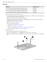
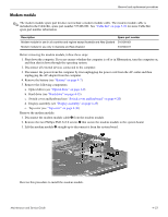
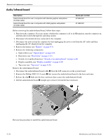
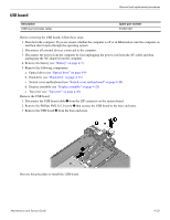
Removal and replacement procedures Top cover Description For use only with white computers equipped with a fingerprint reader For use only with white computers not equipped with a fingerprint reader For use only with black computers equipped with a fingerprint reader For use only with black computers not equipped with a fingerprint reader Spare part number 579159-001 518108-001 579160-001 518788-001 Before removing the top cover, follow these steps: 1. Shut down the computer. If you are unsure whether the computer is off or in Hibernation, turn the computer on, and then shut it down through the operating system. 2. Disconnect all external devices connected to the computer. 3. Disconnect the power from the computer by first unplugging the power cord from the AC outlet and then unplugging the AC adapter from the computer. 4. Remove the battery (see "Battery" on page 4-7). 5. Remove the following components: a. Optical drive (see "Optical drive" on page 4-9) b. Hard drive (see "Hard drive" on page 4-15) c. Switch cover and keyboard (see "Switch cover and keyboard" on page 4-20) d. Display assembly (see "Display assembly" on page 4-25) Remove the top cover: 1. Turn the computer upside-down, with the front toward you. 2. Remove the 10 Phillips PM2.5×7.0 screws 1 that secure the top cover to the computer. 3. Remove the Phillips PM2.5×4.0 screw 2 that secures the top cover to the computer. This screw is in the battery bay. 4-30 Maintenance and Service Guide
-
 1
1 -
2
-
3
-
4
-
5
-
6
-
7
-
8
-
9
-
10
-
11
-
12
-
13
-
14
-
15
-
16
-
17
-
18
-
19
-
20
-
21
-
22
-
23
-
24
-
25
-
26
-
27
-
28
-
29
-
30
-
31
-
32
-
33
-
34
-
35
-
36
-
37
-
38
-
39
-
40
-
41
-
42
-
43
-
44
-
45
-
46
-
47
-
48
-
49
-
50
-
51
-
52
-
53
-
54
-
55
-
56
-
57
-
58
-
59
-
60
-
61
-
62
-
63
-
 64
64 -
 65
65 -
 66
66 -
 67
67 -
 68
68 -
 69
69 -
 70
70 -
 71
71 -
 72
72 -
 73
73 -
 74
74 -
75
-
76
-
77
-
78
-
79
-
80
-
81
-
82
-
83
-
84
-
85
-
86
-
87
-
88
-
89
-
90
-
91
-
92
-
93
-
94
-
95
-
96
-
97
-
98
-
99
-
100
-
101
-
102
-
103
-
104
-
105
-
106
-
107
-
108
-
109
-
110
-
111
-
112
-
113
-
114
-
115
-
116
-
117
-
118
-
119
-
120
-
121
-
122
-
123
-
124
-
125
-
126
-
127
-
128
-
129
 |
 |
