HP Pavilion g6-1000 HP Pavilion G6 Notebook PC - Maintenance and Service Guide - Page 64
and USB board cable, from the system board.
 |
View all HP Pavilion g6-1000 manuals
Add to My Manuals
Save this manual to your list of manuals |
Page 64 highlights
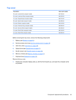
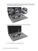
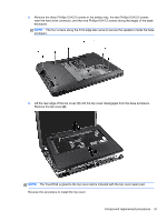
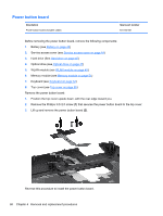
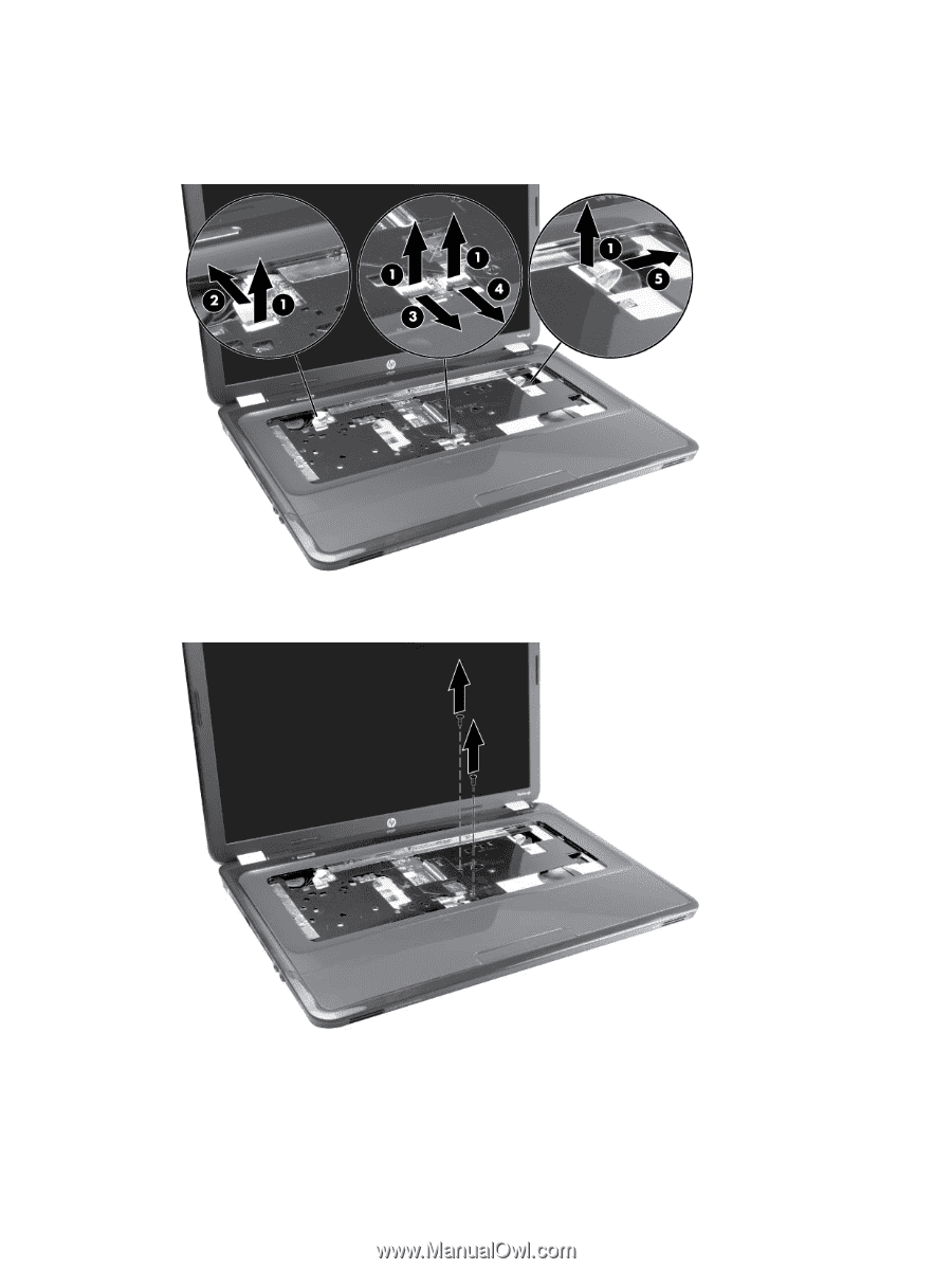
2. Release the three zero insertion force (ZIF) connectors (1) to which the ZIF cables are attached. Then disconnect the power button cable (2), the TouchPad cable (3), the TouchPad button cable (4), and USB board cable (5) from the system board. 3. Remove the two Phillips 5.0×2.5 screws that secure the top cover to the computer. 4. Turn the computer upside down, with the front toward you. 56 Chapter 4 Removal and replacement procedures
-
 1
1 -
2
-
3
-
4
-
5
-
6
-
7
-
8
-
9
-
10
-
11
-
12
-
13
-
14
-
15
-
16
-
17
-
18
-
19
-
20
-
21
-
22
-
23
-
24
-
25
-
26
-
27
-
28
-
29
-
30
-
31
-
32
-
33
-
34
-
35
-
36
-
37
-
38
-
39
-
40
-
41
-
42
-
43
-
44
-
45
-
46
-
47
-
48
-
49
-
50
-
51
-
52
-
53
-
54
-
55
-
56
-
57
-
58
-
 59
59 -
 60
60 -
 61
61 -
 62
62 -
 63
63 -
 64
64 -
 65
65 -
 66
66 -
 67
67 -
 68
68 -
 69
69 -
70
-
71
-
72
-
73
-
74
-
75
-
76
-
77
-
78
-
79
-
80
-
81
-
82
-
83
-
84
-
85
-
86
-
87
-
88
-
89
-
90
-
91
-
92
-
93
-
94
-
95
-
96
-
97
-
98
-
99
-
100
-
101
-
102
-
103
-
104
-
105
-
106
-
107
-
108
-
109
-
110
-
111
-
112
-
113
-
114
-
115
 |
 |
2.
Release the three zero insertion force (ZIF) connectors
(1)
to which the ZIF cables are attached.
Then disconnect the power button cable
(2)
, the TouchPad cable
(3)
, the TouchPad button cable
(4)
, and USB board cable
(5)
from the system board.
3.
Remove the two Phillips 5.0×2.5 screws that secure the top cover to the computer.
4.
Turn the computer upside down, with the front toward you.
56
Chapter 4
Removal and replacement procedures