HP Pavilion g6-1000 HP Pavilion G6 Notebook PC - Maintenance and Service Guide - Page 71
Power connector, Disconnect the power connector cable
 |
View all HP Pavilion g6-1000 manuals
Add to My Manuals
Save this manual to your list of manuals |
Page 71 highlights
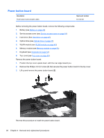
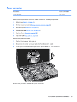
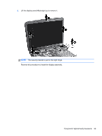
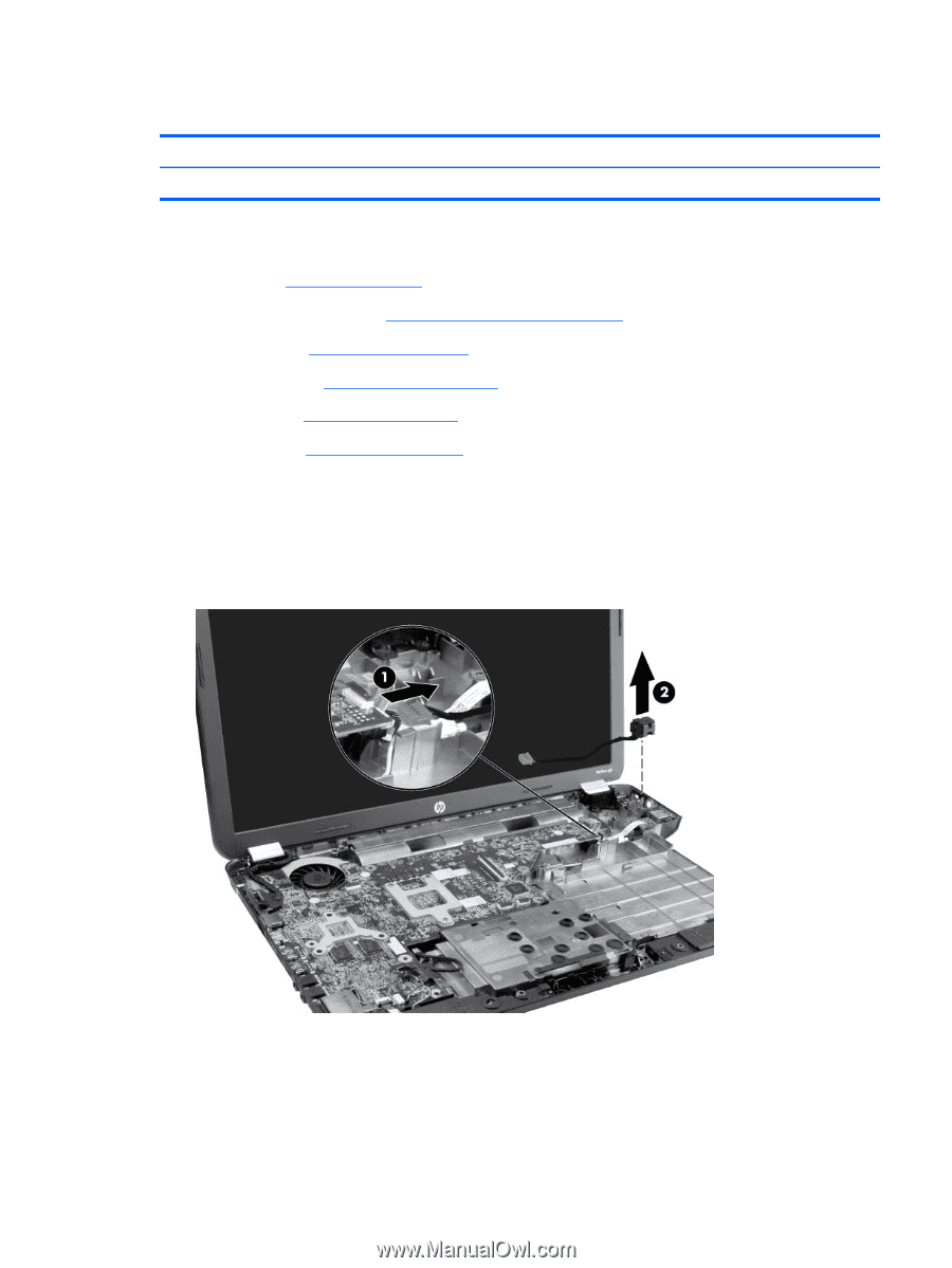
Power connector Description Power connector Spare part number 641137-001 Before removing the power connector cable, remove the following components: 1. Battery (see Battery on page 43) 2. Service access cover (see Service access cover on page 44) 3. Hard drive (see Hard drive on page 45) 4. Optical drive (see Optical drive on page 47) 5. Keyboard (see Keyboard on page 52) 6. Top cover (see Top cover on page 55) Remove the power connector: 1. Position the computer right-side up. 2. Disconnect the power connector cable (1) from the system board. 3. Lift the power connector (2) away from the clips built into the base enclosure. Reverse this procedure to install the power connector. Component replacement procedures 63
-
 1
1 -
2
-
3
-
4
-
5
-
6
-
7
-
8
-
9
-
10
-
11
-
12
-
13
-
14
-
15
-
16
-
17
-
18
-
19
-
20
-
21
-
22
-
23
-
24
-
25
-
26
-
27
-
28
-
29
-
30
-
31
-
32
-
33
-
34
-
35
-
36
-
37
-
38
-
39
-
40
-
41
-
42
-
43
-
44
-
45
-
46
-
47
-
48
-
49
-
50
-
51
-
52
-
53
-
54
-
55
-
56
-
57
-
58
-
59
-
60
-
61
-
62
-
63
-
64
-
65
-
 66
66 -
 67
67 -
 68
68 -
 69
69 -
 70
70 -
 71
71 -
 72
72 -
 73
73 -
 74
74 -
 75
75 -
 76
76 -
77
-
78
-
79
-
80
-
81
-
82
-
83
-
84
-
85
-
86
-
87
-
88
-
89
-
90
-
91
-
92
-
93
-
94
-
95
-
96
-
97
-
98
-
99
-
100
-
101
-
102
-
103
-
104
-
105
-
106
-
107
-
108
-
109
-
110
-
111
-
112
-
113
-
114
-
115
 |
 |
Power connector
Description
Spare part number
Power connector
641137-001
Before removing the power connector cable, remove the following components:
1.
Battery (see
Battery
on page
43
)
2.
Service access cover (see
Service access cover
on page
44
)
3.
Hard drive (see
Hard drive
on page
45
)
4.
Optical drive (see
Optical drive
on page
47
)
5.
Keyboard (see
Keyboard
on page
52
)
6.
Top cover (see
Top cover
on page
55
)
Remove the power connector:
1.
Position the computer right-side up.
2.
Disconnect the power connector cable
(1)
from the system board.
3.
Lift the power connector
(2)
away from the clips built into the base enclosure.
Reverse this procedure to install the power connector.
Component replacement procedures
63