HP Pavilion g6-1000 HP Pavilion G6 Notebook PC - Maintenance and Service Guide - Page 83
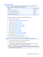
Heat sink assembly
 |
View all HP Pavilion g6-1000 manuals
Add to My Manuals
Save this manual to your list of manuals |
Page 83 highlights
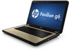
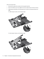
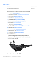
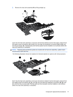
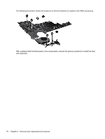
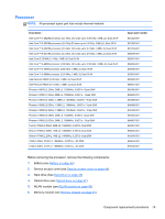
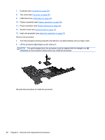
Heat sink assembly NOTE: The heat sink assembly includes replacement thermal material. The heat sink fan is available separately, using spare part number 639460-001. Description For use in AMD UMA computer models For use in Intel UMA HM55 computer models For use in Intel discrete HM55 computer models For use in AMD discrete computer models Spare part number 639463-001 637189-001 637190-001 639462-001 Before removing the heat sink assembly, remove the following components: 1. Battery (see Battery on page 43) 2. Service access cover (see Service access cover on page 44) 3. Hard drive (See Hard drive on page 45) 4. Optical drive (see Optical drive on page 47) 5. WLAN module (see WLAN module on page 49) 6. Memory module (see Memory module on page 51) 7. Keyboard (see Keyboard on page 52) 8. Top cover (see Top cover on page 55) 9. USB board (see USB board on page 62) 10. Display assembly (see Display assembly on page 64) 11. Power connector (see Power connector on page 63) 12. System board (see System board on page 71) Remove the heat sink assembly (heat sink appearance may vary): NOTE: Steps 1 through 5 apply only to computer models equipped with Intel processors. 1. Position the system board right-side up, with the front toward you. 2. Disconnect the fan cable from the system board (1). 3. Follow the sequence embossed on heat sink to loosen the seven Phillips 10.0×2.0 captive screws (2) that secure the heat sink assembly to the system board. NOTE: Due to the adhesive quality of the thermal material located between the heat sink assembly and system board components, it might be necessary to move the heat sink assembly from side to side to detach the assembly. Component replacement procedures 75
-
 1
1 -
2
-
3
-
4
-
5
-
6
-
7
-
8
-
9
-
10
-
11
-
12
-
13
-
14
-
15
-
16
-
17
-
18
-
19
-
20
-
21
-
22
-
23
-
24
-
25
-
26
-
27
-
28
-
29
-
30
-
31
-
32
-
33
-
34
-
35
-
36
-
37
-
38
-
39
-
40
-
41
-
42
-
43
-
44
-
45
-
46
-
47
-
48
-
49
-
50
-
51
-
52
-
53
-
54
-
55
-
56
-
57
-
58
-
59
-
60
-
61
-
62
-
63
-
64
-
65
-
66
-
67
-
68
-
69
-
70
-
71
-
72
-
73
-
74
-
75
-
76
-
77
-
 78
78 -
 79
79 -
 80
80 -
 81
81 -
 82
82 -
 83
83 -
 84
84 -
 85
85 -
 86
86 -
 87
87 -
 88
88 -
89
-
90
-
91
-
92
-
93
-
94
-
95
-
96
-
97
-
98
-
99
-
100
-
101
-
102
-
103
-
104
-
105
-
106
-
107
-
108
-
109
-
110
-
111
-
112
-
113
-
114
-
115
 |
 |