HP Pavilion g6-1000 HP Pavilion G6 Notebook PC - Maintenance and Service Guide - Page 80
from the right edge and pull it away from the base enclosure at an, Remove the system board
 |
View all HP Pavilion g6-1000 manuals
Add to My Manuals
Save this manual to your list of manuals |
Page 80 highlights
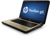
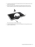
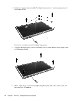
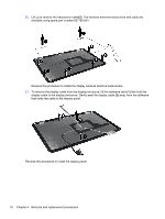
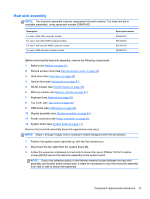
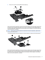
Remove the system board: 1. Disconnect the optical drive connector from the system board (1) . 2. Remove the Phillips 5.0×2.0 screw (2) that secures the system board to the base enclosure. 3. Lift the system board (3) from the right edge and pull it away from the base enclosure at an angle. For AMD computer models, see the following image. For Intel computer models, see the following image. 72 Chapter 4 Removal and replacement procedures
-
 1
1 -
2
-
3
-
4
-
5
-
6
-
7
-
8
-
9
-
10
-
11
-
12
-
13
-
14
-
15
-
16
-
17
-
18
-
19
-
20
-
21
-
22
-
23
-
24
-
25
-
26
-
27
-
28
-
29
-
30
-
31
-
32
-
33
-
34
-
35
-
36
-
37
-
38
-
39
-
40
-
41
-
42
-
43
-
44
-
45
-
46
-
47
-
48
-
49
-
50
-
51
-
52
-
53
-
54
-
55
-
56
-
57
-
58
-
59
-
60
-
61
-
62
-
63
-
64
-
65
-
66
-
67
-
68
-
69
-
70
-
71
-
72
-
73
-
74
-
 75
75 -
 76
76 -
 77
77 -
 78
78 -
 79
79 -
 80
80 -
 81
81 -
 82
82 -
 83
83 -
 84
84 -
 85
85 -
86
-
87
-
88
-
89
-
90
-
91
-
92
-
93
-
94
-
95
-
96
-
97
-
98
-
99
-
100
-
101
-
102
-
103
-
104
-
105
-
106
-
107
-
108
-
109
-
110
-
111
-
112
-
113
-
114
-
115
 |
 |
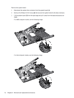
Remove the system board:
1.
Disconnect the optical drive connector from the system board
(1)
.
2.
Remove the Phillips 5.0×2.0 screw
(2)
that secures the system board to the base enclosure.
3.
Lift the system board
(3)
from the right edge and pull it away from the base enclosure at an
angle.
For AMD computer models, see the following image.
For Intel computer models, see the following image.
72
Chapter 4
Removal and replacement procedures