HP Pavilion g6-1000 HP Pavilion G6 Notebook PC - Maintenance and Service Guide - Page 72
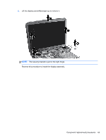
Display assembly, Open the display as far as possible.
 |
View all HP Pavilion g6-1000 manuals
Add to My Manuals
Save this manual to your list of manuals |
Page 72 highlights
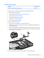
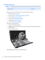
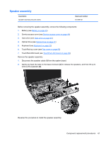
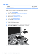
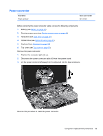
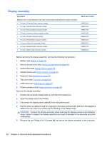
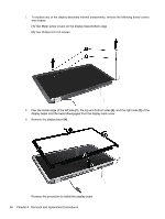
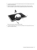
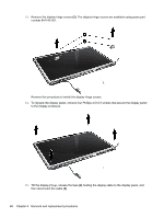
Display assembly Description 39.6-cm (15.6-in) High Definition (HD), light-emitting diode (LED) BrightView display assembly: ● For use in Charcoal Grey computer models ● For use in Ocean Drive computer models ● For use in Sonoma Red computer models ● For use in Luminous Rose computer models ● For use in Pewter computer models ● For use in Pacific Blue computer models ● For use in Pearl Pink computer models ● For use in Sweet Purple computer models ● For use in Butter Gold computer models Spare part number 645523-001 636378-001 645521-001 645522-001 645524-001 645525-001 645526-001 645527-001 645528-001 Before removing the display assembly, remove the following components: 1. Battery (see Battery on page 43) 2. Service access cover (see Service access cover on page 44) 3. Optical drive (see Optical drive on page 47) 4. WLAN module (see WLAN module on page 49) 5. Keyboard (see Keyboard on page 52) 6. Top cover (see Top cover on page 55) 7. USB board (see USB board on page 62) 8. Power connector (see Power connector on page 63) Remove the display assembly: 1. Position the computer display-side up, with the front toward you. 2. Open the display as far as possible. 3. Disconnect the display panel cable (1) from the system board. 4. Pull the antenna cables through the opening in the base enclosure (2), and then disengage the cables from the clip in the routing channel leading to the display hinge. CAUTION: Support the display assembly when removing the display screws in the following steps. Failure to support the display assembly can result in damage to the assembly and other components. 5. Remove the two Phillips 6.0×2.5 screws (3) that secure the display assembly to the computer. 64 Chapter 4 Removal and replacement procedures
-
 1
1 -
2
-
3
-
4
-
5
-
6
-
7
-
8
-
9
-
10
-
11
-
12
-
13
-
14
-
15
-
16
-
17
-
18
-
19
-
20
-
21
-
22
-
23
-
24
-
25
-
26
-
27
-
28
-
29
-
30
-
31
-
32
-
33
-
34
-
35
-
36
-
37
-
38
-
39
-
40
-
41
-
42
-
43
-
44
-
45
-
46
-
47
-
48
-
49
-
50
-
51
-
52
-
53
-
54
-
55
-
56
-
57
-
58
-
59
-
60
-
61
-
62
-
63
-
64
-
65
-
66
-
 67
67 -
 68
68 -
 69
69 -
 70
70 -
 71
71 -
 72
72 -
 73
73 -
 74
74 -
 75
75 -
 76
76 -
 77
77 -
78
-
79
-
80
-
81
-
82
-
83
-
84
-
85
-
86
-
87
-
88
-
89
-
90
-
91
-
92
-
93
-
94
-
95
-
96
-
97
-
98
-
99
-
100
-
101
-
102
-
103
-
104
-
105
-
106
-
107
-
108
-
109
-
110
-
111
-
112
-
113
-
114
-
115
 |
 |