HP Pavilion g6-1000 HP Pavilion G6 Notebook PC - Maintenance and Service Guide - Page 88
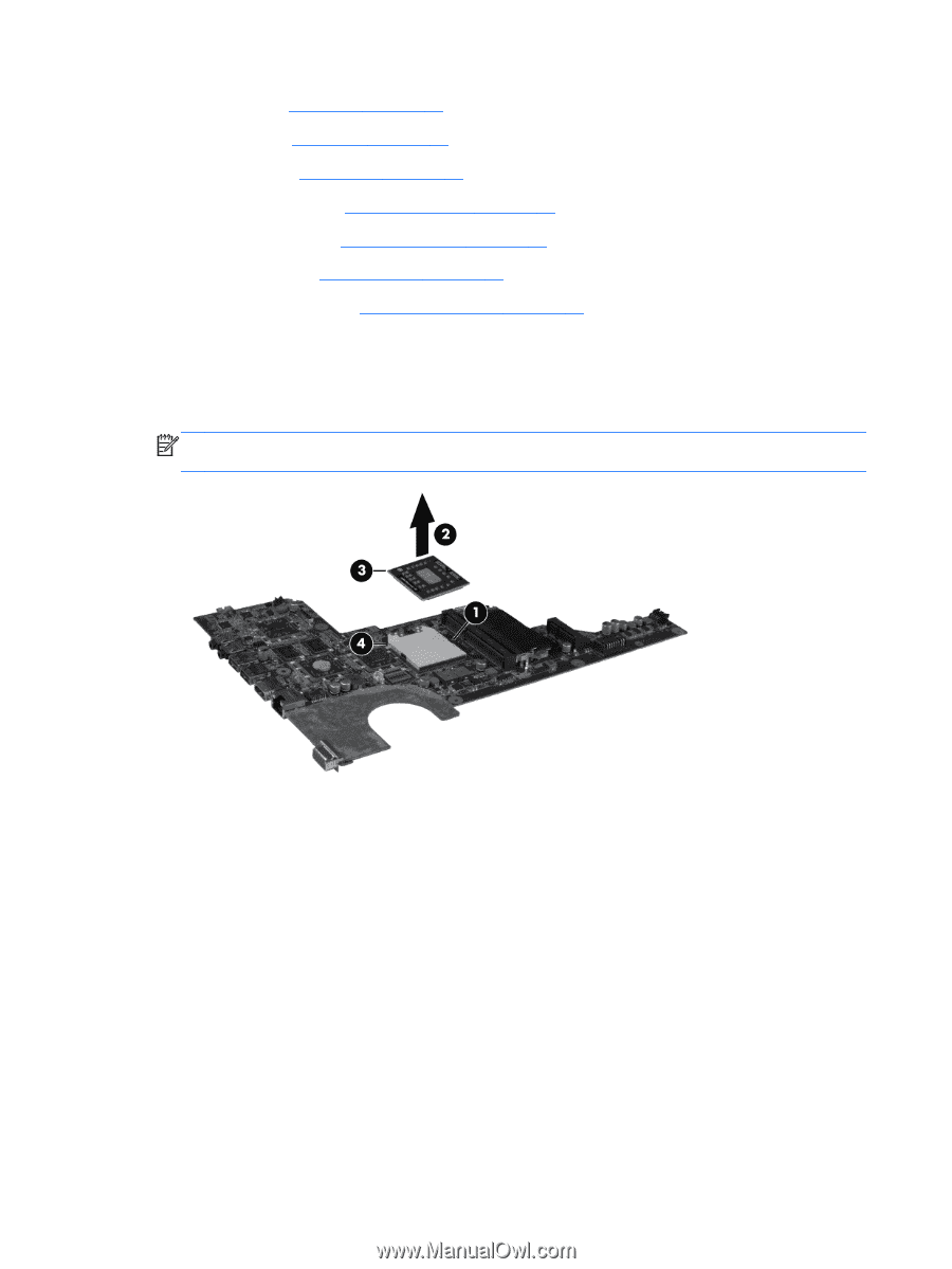
straight up and remove it., one half-turn counterclockwise until you hear a click.
 |
View all HP Pavilion g6-1000 manuals
Add to My Manuals
Save this manual to your list of manuals |
Page 88 highlights
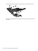
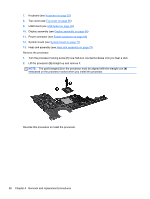
7. Keyboard (see Keyboard on page 52) 8. Top cover (see Top cover on page 55) 9. USB board (see USB board on page 62) 10. Display assembly (see Display assembly on page 64) 11. Power connector (see Power connector on page 63) 12. System board (see System board on page 71) 13. Heat sink assembly (see Heat sink assembly on page 75) Remove the processor: 1. Turn the processor locking screw (1) one half-turn counterclockwise until you hear a click. 2. Lift the processor (2) straight up and remove it. NOTE: The gold triangle (3) on the processor must be aligned with the triangle icon (4) embossed on the processor socket when you install the processor. Reverse this procedure to install the processor. 80 Chapter 4 Removal and replacement procedures
-
 1
1 -
2
-
3
-
4
-
5
-
6
-
7
-
8
-
9
-
10
-
11
-
12
-
13
-
14
-
15
-
16
-
17
-
18
-
19
-
20
-
21
-
22
-
23
-
24
-
25
-
26
-
27
-
28
-
29
-
30
-
31
-
32
-
33
-
34
-
35
-
36
-
37
-
38
-
39
-
40
-
41
-
42
-
43
-
44
-
45
-
46
-
47
-
48
-
49
-
50
-
51
-
52
-
53
-
54
-
55
-
56
-
57
-
58
-
59
-
60
-
61
-
62
-
63
-
64
-
65
-
66
-
67
-
68
-
69
-
70
-
71
-
72
-
73
-
74
-
75
-
76
-
77
-
78
-
79
-
80
-
81
-
82
-
 83
83 -
 84
84 -
 85
85 -
 86
86 -
 87
87 -
 88
88 -
 89
89 -
 90
90 -
 91
91 -
 92
92 -
 93
93 -
94
-
95
-
96
-
97
-
98
-
99
-
100
-
101
-
102
-
103
-
104
-
105
-
106
-
107
-
108
-
109
-
110
-
111
-
112
-
113
-
114
-
115
 |
 |