HP Pavilion g6-1300 HP Pavilion G6 Notebook PC Maintenance and Service Guide - Page 81
Two Phillips 5.0×2.5 screws, and the right side
 |
View all HP Pavilion g6-1300 manuals
Add to My Manuals
Save this manual to your list of manuals |
Page 81 highlights
7. To replace any of the display assembly internal components, remove the following screw covers and screws: (1) Two screw covers on the display bezel bottom edge (2) Two Phillips 5.0×2.5 screws 8. Flex the inside edge of the left side (1), the top and bottom sides (2), and the right side (3) of the display bezel until the bezel disengages from the display back cover. Component replacement procedures 73
-
 1
1 -
2
-
3
-
4
-
5
-
6
-
7
-
8
-
9
-
10
-
11
-
12
-
13
-
14
-
15
-
16
-
17
-
18
-
19
-
20
-
21
-
22
-
23
-
24
-
25
-
26
-
27
-
28
-
29
-
30
-
31
-
32
-
33
-
34
-
35
-
36
-
37
-
38
-
39
-
40
-
41
-
42
-
43
-
44
-
45
-
46
-
47
-
48
-
49
-
50
-
51
-
52
-
53
-
54
-
55
-
56
-
57
-
58
-
59
-
60
-
61
-
62
-
63
-
64
-
65
-
66
-
67
-
68
-
69
-
70
-
71
-
72
-
73
-
74
-
75
-
 76
76 -
 77
77 -
 78
78 -
 79
79 -
 80
80 -
 81
81 -
 82
82 -
 83
83 -
 84
84 -
 85
85 -
 86
86 -
87
-
88
-
89
-
90
-
91
-
92
-
93
-
94
-
95
-
96
-
97
-
98
-
99
-
100
-
101
-
102
-
103
-
104
-
105
-
106
-
107
-
108
-
109
-
110
-
111
-
112
-
113
-
114
-
115
-
116
-
117
-
118
-
119
-
120
-
121
 |
 |
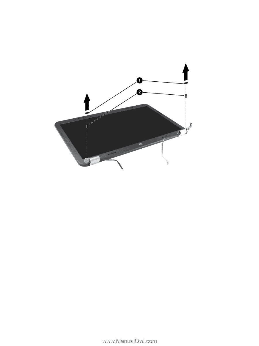
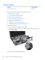
7.
To replace any of the display assembly internal components, remove the following screw covers
and screws:
(1)
Two screw covers on the display bezel bottom edge
(2)
Two Phillips 5.0×2.5 screws
8.
Flex the inside edge of the left side
(1)
, the top and bottom sides
(2)
, and the right side
(3)
of the
display bezel until the bezel disengages from the display back cover.
Component replacement procedures
73