HP Pavilion g6-1300 HP Pavilion G6 Notebook PC Maintenance and Service Guide - Page 87
Remove the system board, TouchPad LED board see
 |
View all HP Pavilion g6-1300 manuals
Add to My Manuals
Save this manual to your list of manuals |
Page 87 highlights
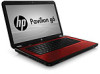
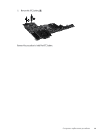
4. Optical drive (see Optical drive on page 52) 5. WLAN module (see WLAN module on page 54) 6. Memory module (see Memory module on page 56) 7. Keyboard (see Keyboard on page 57) 8. Top cover (see Top cover on page 60) 9. USB board (see USB board on page 69) 10. Display assembly (see Display assembly on page 71) 11. Power connector (see Power connector on page 70) 12. TouchPad LED board (see TouchPad LED board on page 67) Remove the system board: 1. Disconnect the optical drive connector from the system board (1) . 2. Remove the Phillips 5.0×2.0 screw (2) that secures the system board to the base enclosure. Component replacement procedures 79
-
 1
1 -
2
-
3
-
4
-
5
-
6
-
7
-
8
-
9
-
10
-
11
-
12
-
13
-
14
-
15
-
16
-
17
-
18
-
19
-
20
-
21
-
22
-
23
-
24
-
25
-
26
-
27
-
28
-
29
-
30
-
31
-
32
-
33
-
34
-
35
-
36
-
37
-
38
-
39
-
40
-
41
-
42
-
43
-
44
-
45
-
46
-
47
-
48
-
49
-
50
-
51
-
52
-
53
-
54
-
55
-
56
-
57
-
58
-
59
-
60
-
61
-
62
-
63
-
64
-
65
-
66
-
67
-
68
-
69
-
70
-
71
-
72
-
73
-
74
-
75
-
76
-
77
-
78
-
79
-
80
-
81
-
 82
82 -
 83
83 -
 84
84 -
 85
85 -
 86
86 -
 87
87 -
 88
88 -
 89
89 -
 90
90 -
 91
91 -
 92
92 -
93
-
94
-
95
-
96
-
97
-
98
-
99
-
100
-
101
-
102
-
103
-
104
-
105
-
106
-
107
-
108
-
109
-
110
-
111
-
112
-
113
-
114
-
115
-
116
-
117
-
118
-
119
-
120
-
121
 |
 |
4.
Optical drive (see
Optical drive
on page
52
)
5.
WLAN module (see
WLAN module
on page
54
)
6.
Memory module (see
Memory module
on page
56
)
7.
Keyboard (see
Keyboard
on page
57
)
8.
Top cover (see
Top cover
on page
60
)
9.
USB board (see
USB board
on page
69
)
10.
Display assembly (see
Display assembly
on page
71
)
11.
Power connector (see
Power connector
on page
70
)
12.
TouchPad LED board (see
TouchPad LED board
on page
67
)
Remove the system board:
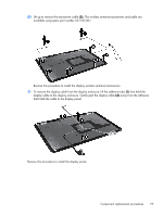
1.
Disconnect the optical drive connector from the system board
(1)
.
2.
Remove the Phillips 5.0×2.0 screw
(2)
that secures the system board to the base enclosure.
Component replacement procedures
79