HP Pavilion g6-1300 HP Pavilion G6 Notebook PC Maintenance and Service Guide - Page 93
Steps 6 through 10 apply only to computer models equipped with AMD processors.
 |
View all HP Pavilion g6-1300 manuals
Add to My Manuals
Save this manual to your list of manuals |
Page 93 highlights
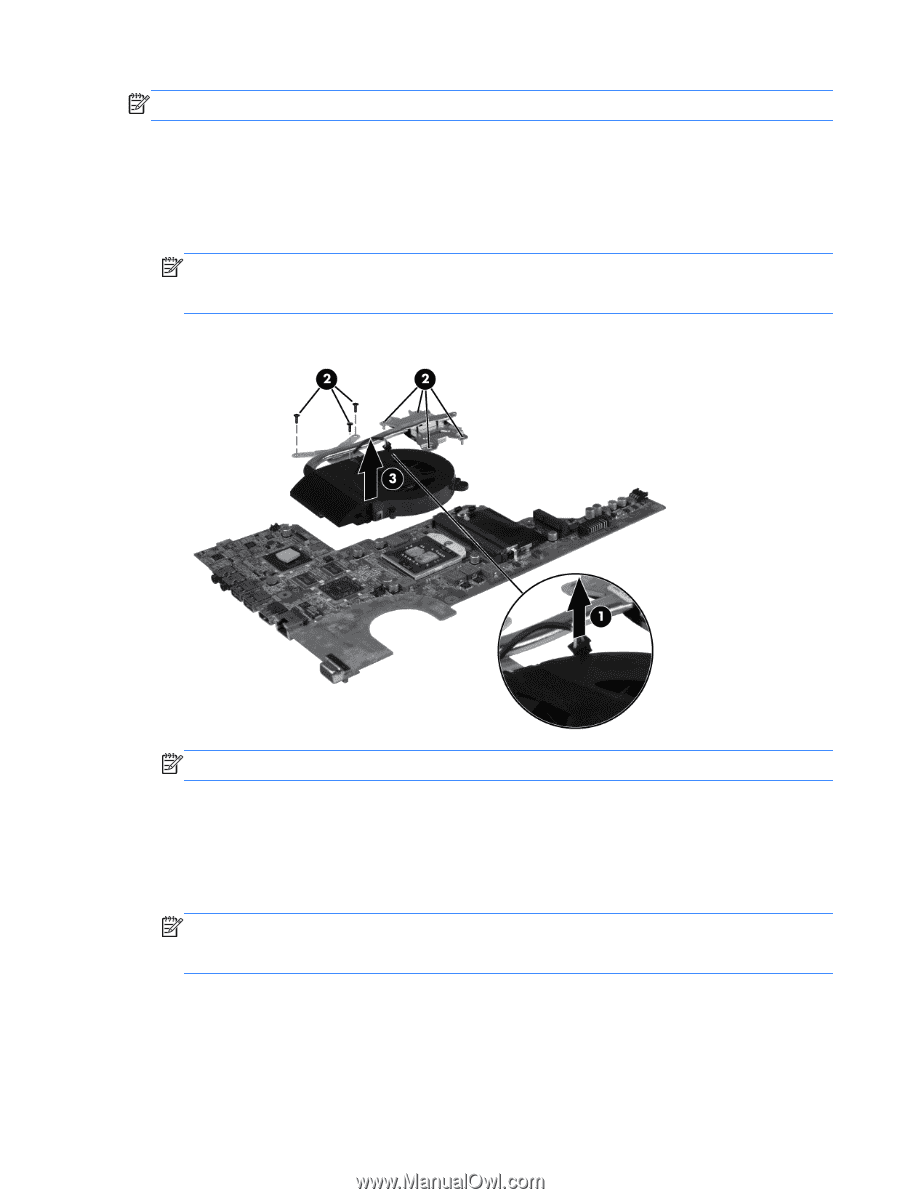
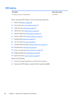
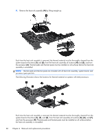
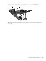
NOTE: Steps 1 through 5 apply only to computer models equipped with Intel processors. 1. Position the system board right-side up, with the front toward you. 2. Disconnect the fan cable from the system board (1). 3. Follow the sequence embossed on heat sink to loosen the seven Phillips 10.0×2.0 captive screws (2) that secure the heat sink assembly to the system board. NOTE: Due to the adhesive quality of the thermal material located between the heat sink assembly and system board components, it might be necessary to move the heat sink assembly from side to side to detach the assembly. 4. Remove the heat sink assembly (3) by lifting it straight up. NOTE: Steps 6 through 10 apply only to computer models equipped with AMD processors. 5. Position the system board right-side up, with the front toward you. 6. Disconnect the fan cable from the system board (1). 7. Remove the three Phillips 3.0×2.0 screws (2) that secure the heat sink assembly to the system board. NOTE: Due to the adhesive quality of the thermal material located between the heat sink assembly and system board components, it might be necessary to move the heat sink assembly from side to side to detach the assembly. 8. Follow the sequence embossed on the heat sink to loosen the three Phillips 10.0×2.0 captive screws (3) that secure the heat sink assembly to the system board. Component replacement procedures 85
-
 1
1 -
2
-
3
-
4
-
5
-
6
-
7
-
8
-
9
-
10
-
11
-
12
-
13
-
14
-
15
-
16
-
17
-
18
-
19
-
20
-
21
-
22
-
23
-
24
-
25
-
26
-
27
-
28
-
29
-
30
-
31
-
32
-
33
-
34
-
35
-
36
-
37
-
38
-
39
-
40
-
41
-
42
-
43
-
44
-
45
-
46
-
47
-
48
-
49
-
50
-
51
-
52
-
53
-
54
-
55
-
56
-
57
-
58
-
59
-
60
-
61
-
62
-
63
-
64
-
65
-
66
-
67
-
68
-
69
-
70
-
71
-
72
-
73
-
74
-
75
-
76
-
77
-
78
-
79
-
80
-
81
-
82
-
83
-
84
-
85
-
86
-
87
-
 88
88 -
 89
89 -
 90
90 -
 91
91 -
 92
92 -
 93
93 -
 94
94 -
 95
95 -
 96
96 -
 97
97 -
 98
98 -
99
-
100
-
101
-
102
-
103
-
104
-
105
-
106
-
107
-
108
-
109
-
110
-
111
-
112
-
113
-
114
-
115
-
116
-
117
-
118
-
119
-
120
-
121
 |
 |