HP Pavilion x360 - 13-a155cl HP Pavilion x360 Convertible PC - Maintenance and - Page 48
Display assembly
 |
View all HP Pavilion x360 - 13-a155cl manuals
Add to My Manuals
Save this manual to your list of manuals |
Page 48 highlights
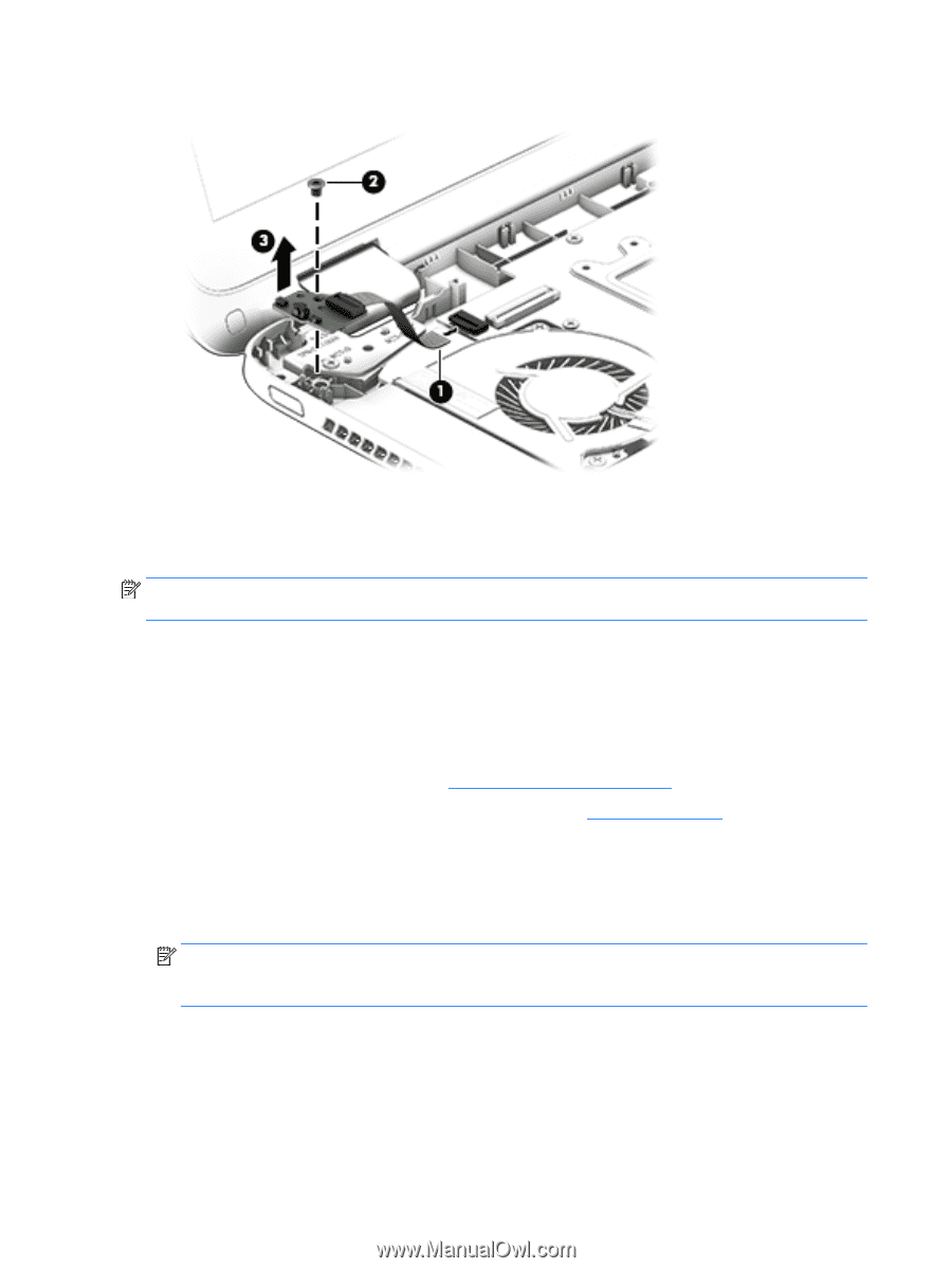
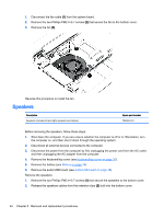
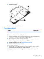
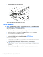
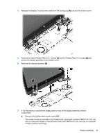
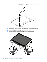
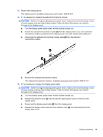
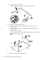
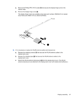
3. Remove the power button board (3) and cable. Reverse this procedure to install the power button board. Display assembly NOTE: The display assembly is spared at the subcomponent level only. For display assembly spare part information, see the individual removal subsections. Before removing the display assembly, follow these steps: 1. Turn off the computer. If you are unsure whether the computer is off or in Hibernation, turn the computer on, and then shut it down through the operating system. 2. Disconnect the power from the computer by unplugging the power cord from the computer. 3. Disconnect all external devices from the computer. 4. Remove the keyboard/top cover (see Keyboard/top cover on page 30). 5. Disconnect the battery cable from the system board (see Battery on page 34). Remove the display assembly: 1. Release the ZIF connector (1) to which the display panel cable is attached, and then disconnect the display panel cable from the system board. 2. Disconnect the WLAN antenna cables (2) from the terminals on the WLAN module. NOTE: The WLAN antenna cable labeled "1" connects to the WLAN module "Main" terminal labeled "1". The WLAN antenna cable labeled "2" connects to the WLAN module "Aux" terminal labeled "2". 3. Release the ZIF connector (3) to which the display TouchScreen cable is attached, and then disconnect the display TouchScreen cable from the system board. 42 Chapter 5 Removal and replacement procedures
-
 1
1 -
2
-
3
-
4
-
5
-
6
-
7
-
8
-
9
-
10
-
11
-
12
-
13
-
14
-
15
-
16
-
17
-
18
-
19
-
20
-
21
-
22
-
23
-
24
-
25
-
26
-
27
-
28
-
29
-
30
-
31
-
32
-
33
-
34
-
35
-
36
-
37
-
38
-
39
-
40
-
41
-
42
-
 43
43 -
 44
44 -
 45
45 -
 46
46 -
 47
47 -
 48
48 -
 49
49 -
 50
50 -
 51
51 -
 52
52 -
 53
53 -
54
-
55
-
56
-
57
-
58
-
59
-
60
-
61
-
62
-
63
-
64
-
65
-
66
-
67
-
68
-
69
-
70
-
71
-
72
-
73
-
74
-
75
-
76
 |
 |