HP Pavilion x360 - 13-a155cl HP Pavilion x360 Convertible PC - Maintenance and - Page 56
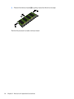
Disconnect the power connector cable, from the system board.
 |
View all HP Pavilion x360 - 13-a155cl manuals
Add to My Manuals
Save this manual to your list of manuals |
Page 56 highlights
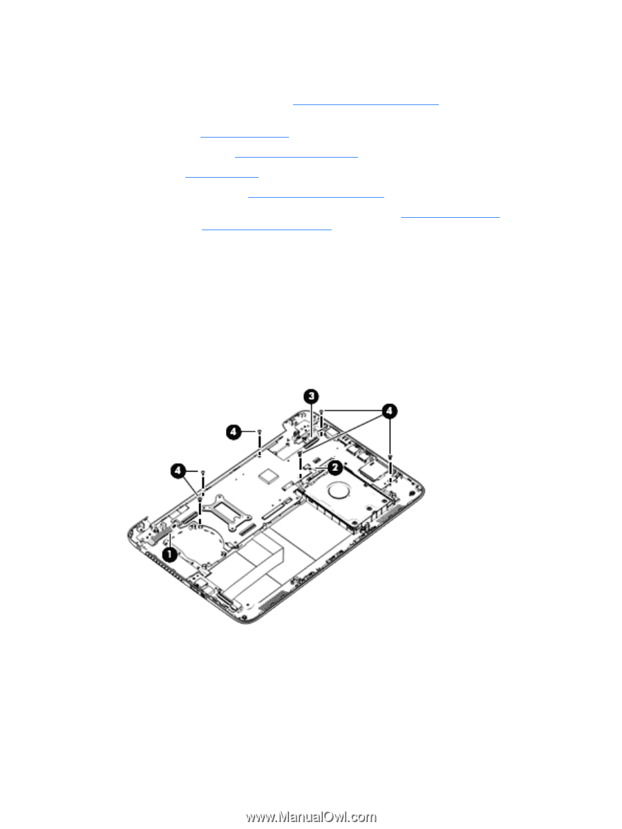
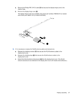
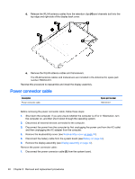
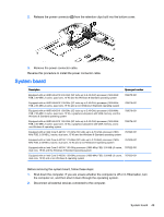
3. Disconnect the power from the computer by first unplugging the power cord from the AC outlet and then unplugging the AC adapter from the computer. 4. Remove the keyboard/top cover (see Keyboard/top cover on page 30), and then remove the following components: a. Battery (see Battery on page 34) b. WLAN module (see WLAN module on page 36) c. Fan (see Fan on page 39) d. Audio/USB board (see Audio/USB board on page 38) When replacing the system board, be sure that the heat sink (see Heat sink on page 51) and the memory modules (see Memory module on page 53) are removed from the defective system board and installed on the replacement system board. Remove the system board: 1. Release the ZIF connector (1) to which the power button board cable is attached, and then disconnect the power button board cable from the system board. 2. Release the ZIF connector (2) to which the hard drive cable is attached, and then disconnect the hard drive cable from the system board. 3. Disconnect the power connector cable (3) from the system board. 4. Remove the six Phillips PM2.4×5.7 screws (4) that secure the system board to the bottom cover. 5. Flex the left side of the bottom cover (1) until the heat sink has clearance for release. 6. Lift the left side of the heat sink (2) and system board until it rests at an angle. 50 Chapter 5 Removal and replacement procedures
-
 1
1 -
2
-
3
-
4
-
5
-
6
-
7
-
8
-
9
-
10
-
11
-
12
-
13
-
14
-
15
-
16
-
17
-
18
-
19
-
20
-
21
-
22
-
23
-
24
-
25
-
26
-
27
-
28
-
29
-
30
-
31
-
32
-
33
-
34
-
35
-
36
-
37
-
38
-
39
-
40
-
41
-
42
-
43
-
44
-
45
-
46
-
47
-
48
-
49
-
50
-
 51
51 -
 52
52 -
 53
53 -
 54
54 -
 55
55 -
 56
56 -
 57
57 -
 58
58 -
 59
59 -
 60
60 -
 61
61 -
62
-
63
-
64
-
65
-
66
-
67
-
68
-
69
-
70
-
71
-
72
-
73
-
74
-
75
-
76
 |
 |