HP Pro 3400 HP Pro 3400 Microtower PC, HP Pro 3405 Microtower PC, HP Pro 3410 - Page 76
Power Switch/LED Assembly
 |
View all HP Pro 3400 manuals
Add to My Manuals
Save this manual to your list of manuals |
Page 76 highlights
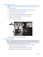
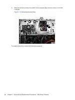
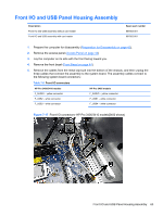
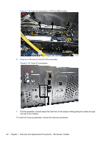
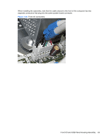
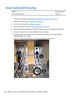
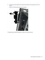
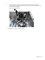
Power Switch/LED Assembly Description Power switch/LED assembly Spare part number 667850-001 1. Prepare the computer for disassembly (Preparation for Disassembly on page 42). 2. Remove the access panel (Access Panel on page 43). 3. Remove the front bezel (Front Bezel on page 44). 4. Remove the optical drive (Removing an Optical Drive on page 61). 5. Disconnect the braided cables from the black system board connector labeled F_PANEL (1). 6. Remove the cable from the metal clip (2) built into the computer. 7. From the inside of the computer, push up on the tab on the bottom of the assembly (3) to disengage it from the computer. Figure 7-21 Removing the power switch cable, disengaging the assembly 66 Chapter 7 Removal and Replacement Procedures - Microtower Chassis
-
 1
1 -
2
-
3
-
4
-
5
-
6
-
7
-
8
-
9
-
10
-
11
-
12
-
13
-
14
-
15
-
16
-
17
-
18
-
19
-
20
-
21
-
22
-
23
-
24
-
25
-
26
-
27
-
28
-
29
-
30
-
31
-
32
-
33
-
34
-
35
-
36
-
37
-
38
-
39
-
40
-
41
-
42
-
43
-
44
-
45
-
46
-
47
-
48
-
49
-
50
-
51
-
52
-
53
-
54
-
55
-
56
-
57
-
58
-
59
-
60
-
61
-
62
-
63
-
64
-
65
-
66
-
67
-
68
-
69
-
70
-
 71
71 -
 72
72 -
 73
73 -
 74
74 -
 75
75 -
 76
76 -
 77
77 -
 78
78 -
 79
79 -
 80
80 -
 81
81 -
82
-
83
-
84
-
85
-
86
-
87
-
88
-
89
-
90
-
91
-
92
-
93
-
94
-
95
-
96
-
97
-
98
-
99
-
100
-
101
-
102
-
103
-
104
-
105
-
106
-
107
-
108
-
109
-
110
-
111
-
112
-
113
-
114
-
115
-
116
-
117
-
118
-
119
-
120
-
121
-
122
-
123
-
124
-
125
-
126
-
127
-
128
-
129
-
130
-
131
-
132
-
133
-
134
-
135
-
136
-
137
-
138
-
139
-
140
-
141
-
142
-
143
-
144
-
145
-
146
-
147
-
148
-
149
-
150
-
151
-
152
-
153
-
154
-
155
-
156
-
157
-
158
-
159
-
160
-
161
-
162
-
163
-
164
-
165
-
166
-
167
-
168
-
169
-
170
-
171
-
172
-
173
-
174
-
175
-
176
-
177
-
178
-
179
-
180
-
181
-
182
-
183
-
184
-
185
-
186
-
187
-
188
-
189
-
190
-
191
-
192
-
193
-
194
-
195
-
196
-
197
-
198
-
199
-
200
 |
 |
