HP Pro 3400 HP Pro 3400 Microtower PC, HP Pro 3405 Microtower PC, HP Pro 3410 - Page 84
CAUTION, the socket are very fragile and any damage to them may require replacing the system board. - bios update
 |
View all HP Pro 3400 manuals
Add to My Manuals
Save this manual to your list of manuals |
Page 84 highlights
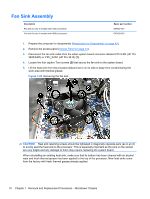
7. If using a new fan sink, remove the protective covering from the bottom of the fan sink and place it in position atop the processor. 8. Secure the fan sink to the system board and system board tray with the 4 captive screws and attach the fan sink control cable to the system board. CAUTION: Heat sink retaining screws should be tightened in diagonally opposite pairs (as in an X) to evenly seat the heat sink on the processor. This is especially important as the pins on the socket are very fragile and any damage to them may require replacing the system board. NOTE: After installing a new processor onto the system board, always update the system ROM to ensure that the latest version of the BIOS is being used on the computer. The latest system ROM BIOS can be found on the Web at: http:\\h18000.www1.hp.com/support/files. 74 Chapter 7 Removal and Replacement Procedures - Microtower Chassis
-
 1
1 -
2
-
3
-
4
-
5
-
6
-
7
-
8
-
9
-
10
-
11
-
12
-
13
-
14
-
15
-
16
-
17
-
18
-
19
-
20
-
21
-
22
-
23
-
24
-
25
-
26
-
27
-
28
-
29
-
30
-
31
-
32
-
33
-
34
-
35
-
36
-
37
-
38
-
39
-
40
-
41
-
42
-
43
-
44
-
45
-
46
-
47
-
48
-
49
-
50
-
51
-
52
-
53
-
54
-
55
-
56
-
57
-
58
-
59
-
60
-
61
-
62
-
63
-
64
-
65
-
66
-
67
-
68
-
69
-
70
-
71
-
72
-
73
-
74
-
75
-
76
-
77
-
78
-
 79
79 -
 80
80 -
 81
81 -
 82
82 -
 83
83 -
 84
84 -
 85
85 -
 86
86 -
 87
87 -
 88
88 -
 89
89 -
90
-
91
-
92
-
93
-
94
-
95
-
96
-
97
-
98
-
99
-
100
-
101
-
102
-
103
-
104
-
105
-
106
-
107
-
108
-
109
-
110
-
111
-
112
-
113
-
114
-
115
-
116
-
117
-
118
-
119
-
120
-
121
-
122
-
123
-
124
-
125
-
126
-
127
-
128
-
129
-
130
-
131
-
132
-
133
-
134
-
135
-
136
-
137
-
138
-
139
-
140
-
141
-
142
-
143
-
144
-
145
-
146
-
147
-
148
-
149
-
150
-
151
-
152
-
153
-
154
-
155
-
156
-
157
-
158
-
159
-
160
-
161
-
162
-
163
-
164
-
165
-
166
-
167
-
168
-
169
-
170
-
171
-
172
-
173
-
174
-
175
-
176
-
177
-
178
-
179
-
180
-
181
-
182
-
183
-
184
-
185
-
186
-
187
-
188
-
189
-
190
-
191
-
192
-
193
-
194
-
195
-
196
-
197
-
198
-
199
-
200
 |
 |
