HP ProBook 635 Maintenance and Service Guide - Page 51
WWAN module, Remove the Phillips M2.0 × 2.0 screw
 |
View all HP ProBook 635 manuals
Add to My Manuals
Save this manual to your list of manuals |
Page 51 highlights
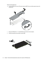
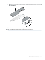
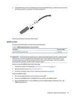
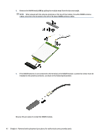
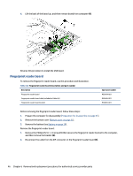
3. If the WLAN antenna is not connected to the terminal on the WLAN module, install a protective sleeve on the antenna connector, as shown in the following illustration. Reverse this procedure to install the WLAN module. WWAN module To remove the WWAN module, use this procedure and illustration. Table 6-3 WWAN module descriptions and part numbers Description Intel XMM 7360 LTE-Advanced (Cat 9) Spare part number L15398-005 IMPORTANT: To prevent an unresponsive system, replace the wireless module only with a wireless module authorized for use in the computer by the governmental agency that regulates wireless devices in your country or region. If you replace the module and then receive a warning message, remove the module to restore device functionality, and then contact technical support. Before removing the WWAN module, follow these steps: 1. Prepare the computer for disassembly (Preparation for disassembly on page 31). 2. Remove the bottom cover (Bottom cover on page 31). 3. Disconnect the battery cable from the system board (see Battery on page 38). Remove the WWAN module: 1. Remove the protective piece from the antenna connectors (1). 2. Disconnect the WWAN antenna cables (2) from the terminals on the WWAN module. 3. Remove the Phillips M2.0 × 2.0 screw (3) that secures the WWAN module to the bottom cover. (The WWAN module tilts up.) Component replacement procedures 41
-
 1
1 -
2
-
3
-
4
-
5
-
6
-
7
-
8
-
9
-
10
-
11
-
12
-
13
-
14
-
15
-
16
-
17
-
18
-
19
-
20
-
21
-
22
-
23
-
24
-
25
-
26
-
27
-
28
-
29
-
30
-
31
-
32
-
33
-
34
-
35
-
36
-
37
-
38
-
39
-
40
-
41
-
42
-
43
-
44
-
45
-
 46
46 -
 47
47 -
 48
48 -
 49
49 -
 50
50 -
 51
51 -
 52
52 -
 53
53 -
 54
54 -
 55
55 -
 56
56 -
57
-
58
-
59
-
60
-
61
-
62
-
63
-
64
-
65
-
66
-
67
-
68
-
69
-
70
-
71
-
72
-
73
-
74
-
75
-
76
-
77
-
78
-
79
-
80
-
81
-
82
-
83
-
84
-
85
-
86
-
87
-
88
-
89
-
90
-
91
-
92
-
93
-
94
-
95
-
96
-
97
-
98
-
99
-
100
-
101
-
102
-
103
-
104
-
105
-
106
 |
 |
