HP ProBook 635 Maintenance and Service Guide - Page 59
Heat sink, Remove the heat sink
 |
View all HP ProBook 635 manuals
Add to My Manuals
Save this manual to your list of manuals |
Page 59 highlights
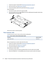
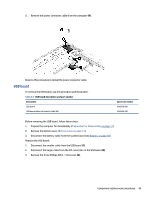
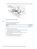
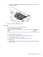
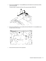
3. Loosen the three Phillips captive screws (3) that secure the fan to the computer, and then remove the fan from the computer (4). Reverse this procedure to install the fan assembly. Heat sink To remove the heat sink, use these procedures and illustrations. Table 6-11 Heat sink descriptions and part numbers Description Heat sink Spare part number M30651-001 Before removing the heat sink, follow these steps: 1. Prepare the computer for disassembly (Preparation for disassembly on page 31). 2. Remove the bottom cover (Bottom cover on page 31). 3. Disconnect the battery cable from the system board (see Battery on page 38). Remove the heat sink: 1. In the order indicated on the heat sink, loosen the four captive Phillips screws (1) that secure the heat sink to the computer. Component replacement procedures 49
-
 1
1 -
2
-
3
-
4
-
5
-
6
-
7
-
8
-
9
-
10
-
11
-
12
-
13
-
14
-
15
-
16
-
17
-
18
-
19
-
20
-
21
-
22
-
23
-
24
-
25
-
26
-
27
-
28
-
29
-
30
-
31
-
32
-
33
-
34
-
35
-
36
-
37
-
38
-
39
-
40
-
41
-
42
-
43
-
44
-
45
-
46
-
47
-
48
-
49
-
50
-
51
-
52
-
53
-
 54
54 -
 55
55 -
 56
56 -
 57
57 -
 58
58 -
 59
59 -
 60
60 -
 61
61 -
 62
62 -
 63
63 -
 64
64 -
65
-
66
-
67
-
68
-
69
-
70
-
71
-
72
-
73
-
74
-
75
-
76
-
77
-
78
-
79
-
80
-
81
-
82
-
83
-
84
-
85
-
86
-
87
-
88
-
89
-
90
-
91
-
92
-
93
-
94
-
95
-
96
-
97
-
98
-
99
-
100
-
101
-
102
-
103
-
104
-
105
-
106
 |
 |
