HP ProBook 6440b HP ProBook 6545b, 6540b, 6445b and 6440b Notebook PC - Mainte - Page 115
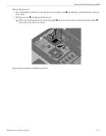
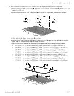
Lift the display assembly, straight up and remove it.
 |
View all HP ProBook 6440b manuals
Add to My Manuals
Save this manual to your list of manuals |
Page 115 highlights
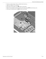
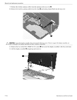
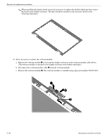
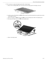
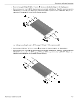
Removal and replacement procedures 9. Release the wireless antenna cables from the opening in the top cover 1. 10. Remove the wireless antenna cables from the clips 2 and routing channel built into the top cover. Ä CAUTION: Support the display assembly when removing the following screws. Failure to support the display assembly can result in damage to the display assembly and other computer components. 11. Remove the two slotted Torx T8M2.5×11.0 screws 1 that secure the display assembly to the base enclosure. 12. Lift the display assembly 2 straight up and remove it. 4-46 Maintenance and Service Guide
-
 1
1 -
2
-
3
-
4
-
5
-
6
-
7
-
8
-
9
-
10
-
11
-
12
-
13
-
14
-
15
-
16
-
17
-
18
-
19
-
20
-
21
-
22
-
23
-
24
-
25
-
26
-
27
-
28
-
29
-
30
-
31
-
32
-
33
-
34
-
35
-
36
-
37
-
38
-
39
-
40
-
41
-
42
-
43
-
44
-
45
-
46
-
47
-
48
-
49
-
50
-
51
-
52
-
53
-
54
-
55
-
56
-
57
-
58
-
59
-
60
-
61
-
62
-
63
-
64
-
65
-
66
-
67
-
68
-
69
-
70
-
71
-
72
-
73
-
74
-
75
-
76
-
77
-
78
-
79
-
80
-
81
-
82
-
83
-
84
-
85
-
86
-
87
-
88
-
89
-
90
-
91
-
92
-
93
-
94
-
95
-
96
-
97
-
98
-
99
-
100
-
101
-
102
-
103
-
104
-
105
-
106
-
107
-
108
-
109
-
 110
110 -
 111
111 -
 112
112 -
 113
113 -
 114
114 -
 115
115 -
 116
116 -
 117
117 -
 118
118 -
 119
119 -
 120
120 -
121
-
122
-
123
-
124
-
125
-
126
-
127
-
128
-
129
-
130
-
131
-
132
-
133
-
134
-
135
-
136
-
137
-
138
-
139
-
140
-
141
-
142
-
143
-
144
-
145
-
146
-
147
-
148
-
149
-
150
-
151
-
152
-
153
-
154
-
155
-
156
-
157
-
158
-
159
-
160
-
161
-
162
-
163
-
164
-
165
-
166
-
167
-
168
-
169
-
170
-
171
-
172
-
173
-
174
-
175
-
176
-
177
-
178
-
179
-
180
-
181
-
182
-
183
-
184
-
185
-
186
-
187
-
188
-
189
-
190
-
191
-
192
-
193
-
194
-
195
-
196
-
197
-
198
-
199
-
200
-
201
-
202
-
203
-
204
-
205
-
206
-
207
-
208
-
209
-
210
-
211
-
212
-
213
-
214
-
215
-
216
-
217
-
218
-
219
-
220
-
221
 |
 |

4–46
Maintenance and Service Guide
Removal and replacement procedures
9. Release the wireless antenna cables from the opening in the top cover
1
.
10. Remove the wireless antenna cables from the clips
2
and routing channel built into the top cover.
Ä
CAUTION:
Support the display assembly when removing the following screws. Failure to support the display assembly can
result in damage to the display assembly and other computer components.
11. Remove the two slotted Torx T8M2.5×11.0 screws
1
that secure the display assembly to the base enclosure.
12. Lift the display assembly
2
straight up and remove it.