HP ProBook 6440b HP ProBook 6545b, 6540b, 6445b and 6440b Notebook PC - Mainte - Page 220
Universal Serial Bus USB port
 |
View all HP ProBook 6440b manuals
Add to My Manuals
Save this manual to your list of manuals |
Page 220 highlights
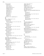
Index RTC battery removal 4-29 spare part numbers 3-11, 3-23, 3-27, 4-29 Rubber Kit, spare part number 3-14, 3-27, 4-6 S Screw Kit, spare part number 3-22, 3-27 screw listing 7-1 security cable slot 2-14, 2-17 Security menu 5-4, 5-10, 5-16 security, product description 1-7 serial connector removal 4-75 spare part numbers 3-13, 3-26, 3-34, 4-75 serial port connector pinout 9-4 location 2-13 service considerations 4-1 serviceability, product description 1-8 SIM slot 2-18 SIM, removal 4-8 Smart Card Reader location 2-16 removal 4-59 spare part number 3-12, 3-33, 4-59 solid-state drive removal 4-11 spare part numbers 3-14, 3-20, 3-26, 3-36, 4-11 speaker assembly removal 4-65 spare part numbers 3-12, 3-27, 4-65 speakers 2-12 specifications Blu-ray ROM DVD±RW SuperMulti Double-Layer Drive 6-4 computer 6-1 display assembly 6-3 DVD±RW and CD-RW SuperMulti Double-Layer Drive 6-5 DVD-ROM Drive 6-6 hard drive 6-4 optical drive 6-4, 6-5, 6-6 system DMA 6-7 system I/O address 6-9 system interrupt 6-8 system memory map 6-7 switch cover removal 4-30 spare part numbers 3-5, 3-26, 3-34, 4-30 system board removal 4-71 spare part numbers 3-13, 3-26, 3-33, 3-36, 4-71 System Configuration menu 5-5, 5-11, 5-17 system DMA specifications 6-7 system I/O address specifications 6-9 system interrupt specifications 6-8 system memory map specifications 6-7 system recovery 8-1 T tools required 4-1 top cover removal 4-56 spare part numbers 3-12, 3-26, 3-34, 4-56 TouchPad location 2-5 removal 4-35 spare part numbers 3-11, 3-26, 3-34, 4-35 TouchPad board cable, illustrated 3-17 TouchPad buttons 2-5 TouchPad scroll zone 2-5 U Universal Serial Bus (USB) port connector pinout 9-4 location 2-13, 2-14, 2-15, 2-16 Upgrade bay 2-13, 2-14 V vents 2-15, 2-16, 2-18 volume down button 2-7, 2-8 volume down light 2-9, 2-11 volume mute button 2-6, 2-8 volume mute light 2-9, 2-11 volume up button 2-7, 2-8 volume up light 2-9, 2-11 W warranty period 3-1, 4-5 webcam location 2-2 product description 1-4 webcam cable, illustrated 3-19 webcam light 2-2, 2-12 webcam module illustrated 3-19 removal 4-48 spare part number 3-19, 3-25, 4-48 Windows applications key 2-3, 2-4 Windows logo key 2-3, 2-4 wireless antennas disconnecting 4-18, 4-19 illustrated 3-19 locations 2-2 removal 4-53, 4-54 wireless button 2-6, 2-8 wireless light 2-8, 2-10, 2-12 Maintenance and Service Guide Index-5
-
 1
1 -
2
-
3
-
4
-
5
-
6
-
7
-
8
-
9
-
10
-
11
-
12
-
13
-
14
-
15
-
16
-
17
-
18
-
19
-
20
-
21
-
22
-
23
-
24
-
25
-
26
-
27
-
28
-
29
-
30
-
31
-
32
-
33
-
34
-
35
-
36
-
37
-
38
-
39
-
40
-
41
-
42
-
43
-
44
-
45
-
46
-
47
-
48
-
49
-
50
-
51
-
52
-
53
-
54
-
55
-
56
-
57
-
58
-
59
-
60
-
61
-
62
-
63
-
64
-
65
-
66
-
67
-
68
-
69
-
70
-
71
-
72
-
73
-
74
-
75
-
76
-
77
-
78
-
79
-
80
-
81
-
82
-
83
-
84
-
85
-
86
-
87
-
88
-
89
-
90
-
91
-
92
-
93
-
94
-
95
-
96
-
97
-
98
-
99
-
100
-
101
-
102
-
103
-
104
-
105
-
106
-
107
-
108
-
109
-
110
-
111
-
112
-
113
-
114
-
115
-
116
-
117
-
118
-
119
-
120
-
121
-
122
-
123
-
124
-
125
-
126
-
127
-
128
-
129
-
130
-
131
-
132
-
133
-
134
-
135
-
136
-
137
-
138
-
139
-
140
-
141
-
142
-
143
-
144
-
145
-
146
-
147
-
148
-
149
-
150
-
151
-
152
-
153
-
154
-
155
-
156
-
157
-
158
-
159
-
160
-
161
-
162
-
163
-
164
-
165
-
166
-
167
-
168
-
169
-
170
-
171
-
172
-
173
-
174
-
175
-
176
-
177
-
178
-
179
-
180
-
181
-
182
-
183
-
184
-
185
-
186
-
187
-
188
-
189
-
190
-
191
-
192
-
193
-
194
-
195
-
196
-
197
-
198
-
199
-
200
-
201
-
202
-
203
-
204
-
205
-
206
-
207
-
208
-
209
-
210
-
211
-
212
-
213
-
214
-
 215
215 -
 216
216 -
 217
217 -
 218
218 -
 219
219 -
 220
220 -
 221
221
 |
 |