HP ProDesk 600 G5 Maintenance and Service Guide - Page 52
Serial connector module, Disconnect the serial connector module cable
 |
View all HP ProDesk 600 G5 manuals
Add to My Manuals
Save this manual to your list of manuals |
Page 52 highlights
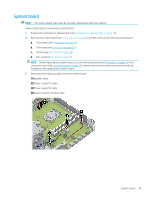
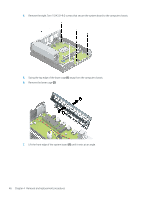
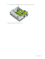
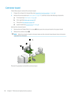
Serial connector module Follow these steps to remove the serial connector module: 1. Prepare the computer for disassembly (see Preparation for disassembly on page 30). 2. Remove the access panel (see Access panel on page 31), and then remove the following components: a. Front bezel (see Front bezel on page 33) b. Drive cage (see Drive cage on page 36) c. Shroud (see Fan shroud on page 40) Remove the serial connector module: 1. Disconnect the serial connector module cable (1) from the system board. 2. Remove the two 3/16-in. screw locks (2) that secure the serial connector module to the computer chassis. 3. Remove the serial connector module (3). Reverse this procedure to install the serial connector module. 44 Chapter 4 Removal and replacement procedures
-
 1
1 -
2
-
3
-
4
-
5
-
6
-
7
-
8
-
9
-
10
-
11
-
12
-
13
-
14
-
15
-
16
-
17
-
18
-
19
-
20
-
21
-
22
-
23
-
24
-
25
-
26
-
27
-
28
-
29
-
30
-
31
-
32
-
33
-
34
-
35
-
36
-
37
-
38
-
39
-
40
-
41
-
42
-
43
-
44
-
45
-
46
-
 47
47 -
 48
48 -
 49
49 -
 50
50 -
 51
51 -
 52
52 -
 53
53 -
 54
54 -
 55
55 -
 56
56 -
 57
57 -
58
-
59
-
60
-
61
-
62
-
63
-
64
-
65
-
66
-
67
-
68
-
69
-
70
-
71
-
72
-
73
-
74
-
75
-
76
-
77
-
78
-
79
-
80
-
81
-
82
-
83
-
84
-
85
-
86
-
87
-
88
-
89
-
90
-
91
-
92
-
93
-
94
-
95
-
96
-
97
-
98
-
99
-
100
-
101
-
102
-
103
-
104
-
105
-
106
-
107
-
108
-
109
-
110
-
111
-
112
-
113
-
114
-
115
-
116
-
117
-
118
-
119
-
120
-
121
-
122
-
123
-
124
-
125
 |
 |
