HP ProDesk 600 G5 Maintenance and Service Guide - Page 54
until it rests at an angle., Removal and replacement procedures
 |
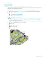
View all HP ProDesk 600 G5 manuals
Add to My Manuals
Save this manual to your list of manuals |
Page 54 highlights
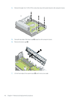
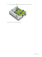
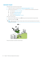
4. Remove the eight Torx-15 M3.0×9.0 screws that secure the system board to the computer chassis. 5. Swing the top edge of the lower cage (1) away from the computer chassis. 6. Remove the lower cage (2). 7. Lift the front edge of the system board (1) until it rests at an angle. 46 Chapter 4 Removal and replacement procedures
-
 1
1 -
2
-
3
-
4
-
5
-
6
-
7
-
8
-
9
-
10
-
11
-
12
-
13
-
14
-
15
-
16
-
17
-
18
-
19
-
20
-
21
-
22
-
23
-
24
-
25
-
26
-
27
-
28
-
29
-
30
-
31
-
32
-
33
-
34
-
35
-
36
-
37
-
38
-
39
-
40
-
41
-
42
-
43
-
44
-
45
-
46
-
47
-
48
-
 49
49 -
 50
50 -
 51
51 -
 52
52 -
 53
53 -
 54
54 -
 55
55 -
 56
56 -
 57
57 -
 58
58 -
 59
59 -
60
-
61
-
62
-
63
-
64
-
65
-
66
-
67
-
68
-
69
-
70
-
71
-
72
-
73
-
74
-
75
-
76
-
77
-
78
-
79
-
80
-
81
-
82
-
83
-
84
-
85
-
86
-
87
-
88
-
89
-
90
-
91
-
92
-
93
-
94
-
95
-
96
-
97
-
98
-
99
-
100
-
101
-
102
-
103
-
104
-
105
-
106
-
107
-
108
-
109
-
110
-
111
-
112
-
113
-
114
-
115
-
116
-
117
-
118
-
119
-
120
-
121
-
122
-
123
-
124
-
125
 |
 |

4.
Remove the eight Torx-15 M3.0×9.0 screws that secure the system board to the computer chassis.
5.
Swing the top edge of the lower cage
(1)
away from the computer chassis.
6.
Remove the lower cage
(2)
.
7.
Lift the front edge of the system board
(1)
until it rests at an angle.
46
Chapter 4
Removal and replacement procedures