HP ProLiant ML110 ProLiant ML110 Generation 2 Server Maintenance and Service G - Page 72
I/O Device Connection, System Board Components, Connecting I/O devices
 |
View all HP ProLiant ML110 manuals
Add to My Manuals
Save this manual to your list of manuals |
Page 72 highlights
Connectors, Switches, and LEDs I/O Device Connection The color-coded I/O ports on the rear panel are each marked with icons that indicate the kind of devices that can be connected to them. Figure 4-3: Connecting I/O devices System Board Components Figure 4-4 and Table 4-3 show and describe the components on the system board. Figure 4-4: System board components 4-4 HP ProLiant ML110 Generation 2 Server Maintenance and Service Guide
-
 1
1 -
2
-
3
-
4
-
5
-
6
-
7
-
8
-
9
-
10
-
11
-
12
-
13
-
14
-
15
-
16
-
17
-
18
-
19
-
20
-
21
-
22
-
23
-
24
-
25
-
26
-
27
-
28
-
29
-
30
-
31
-
32
-
33
-
34
-
35
-
36
-
37
-
38
-
39
-
40
-
41
-
42
-
43
-
44
-
45
-
46
-
47
-
48
-
49
-
50
-
51
-
52
-
53
-
54
-
55
-
56
-
57
-
58
-
59
-
60
-
61
-
62
-
63
-
64
-
65
-
66
-
 67
67 -
 68
68 -
 69
69 -
 70
70 -
 71
71 -
 72
72 -
 73
73 -
 74
74 -
 75
75 -
 76
76 -
 77
77 -
78
-
79
-
80
-
81
-
82
-
83
-
84
-
85
-
86
-
87
-
88
-
89
-
90
-
91
-
92
-
93
-
94
-
95
-
96
-
97
-
98
 |
 |
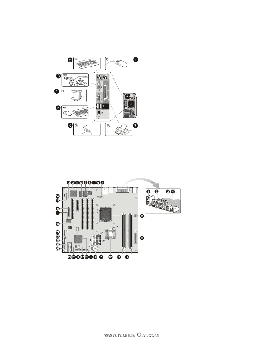
Connectors, Switches, and LEDs
I/O Device Connection
The color-coded I/O ports on the rear panel are each marked with icons that indicate the kind
of devices that can be connected to them.
Figure 4-3:
Connecting I/O devices
System Board Components
Figure 4-4 and Table 4-3 show and describe the components on the system board.
Figure 4-4:
System board components
4-4
HP ProLiant ML110 Generation 2 Server Maintenance and Service Guide