HP ProLiant ML110 ProLiant ML110 Generation 2 Server Maintenance and Service G - Page 73
Table 4-3, System Board Components
 |
View all HP ProLiant ML110 manuals
Add to My Manuals
Save this manual to your list of manuals |
Page 73 highlights
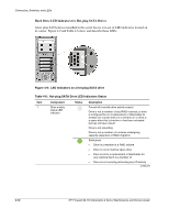
Connectors, Switches, and LEDs Table 4-3: System Board Components Item 1 2 3 4 5 6 7 8 9 10 11 12 13 14 15 16 17 18 19 20 21 22 23 24 25 Component Code CN1 CN2 CN5 CN6 CN7 CN10 PCI1 - PCI3 U13 U17 U18 PCI4 U22 PCI5 CN22 CN24 CN20 U34 CN21 CN27 CN17 CN18 CN13 CN16 SATA0 - SATA3 BZ1 Component Top: PS/2 mouse port Bottom: PS/2 keyboard port Top: Parallel port Left: Video port Right: Serial port Rear USB 2.0 ports (two) LAN port (RJ-45) 3-pin processor fan connector 3-pin system fan connector (rear) 64-bit/100-MHz, 3.3-V PCI-X bus slots (three) Intel GD8254IPI GbE controller SMSC LPC47M192 Super I/O chipset VGA frame buffer PCI-Express x4 bus slot ATI Rage XL VGA chipset 32-bit/33-MHz, 5-V PCI bus slot 9-pin BMC COM connector 9-pin extension serial connector (COM2) IPMI connector BIOS flash EEPROM (Electrically Erasable Programmable Read-Only Memory) Connector for the front USB 2.0 ports Internal USB connector Internal USB connector (for internal USB tape use) Connector for the diskette drive option 4-pin SCSI LED connector 9-pin front panel board connector 7-pin 150-MBps SATA connectors (four) Internal buzzer continued HP ProLiant ML110 Generation 2 Server Maintenance and Service Guide 4-5
-
 1
1 -
2
-
3
-
4
-
5
-
6
-
7
-
8
-
9
-
10
-
11
-
12
-
13
-
14
-
15
-
16
-
17
-
18
-
19
-
20
-
21
-
22
-
23
-
24
-
25
-
26
-
27
-
28
-
29
-
30
-
31
-
32
-
33
-
34
-
35
-
36
-
37
-
38
-
39
-
40
-
41
-
42
-
43
-
44
-
45
-
46
-
47
-
48
-
49
-
50
-
51
-
52
-
53
-
54
-
55
-
56
-
57
-
58
-
59
-
60
-
61
-
62
-
63
-
64
-
65
-
66
-
67
-
 68
68 -
 69
69 -
 70
70 -
 71
71 -
 72
72 -
 73
73 -
 74
74 -
 75
75 -
 76
76 -
 77
77 -
 78
78 -
79
-
80
-
81
-
82
-
83
-
84
-
85
-
86
-
87
-
88
-
89
-
90
-
91
-
92
-
93
-
94
-
95
-
96
-
97
-
98
 |
 |
