HP ProLiant MicroServer Gen8 HP ProLiant MicroServer Gen8 User Guide - Page 11
DIMM slot locations, System maintenance switch, Position, Default, Function
 |
View all HP ProLiant MicroServer Gen8 manuals
Add to My Manuals
Save this manual to your list of manuals |
Page 11 highlights
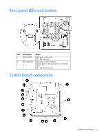
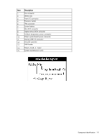
DIMM slot locations DIMM slots are numbered sequentially (1 through 4) for the processor. The supported AMP modes use the letter assignments for population guidelines. System maintenance switch Position S1 S2 S3 S4 S5 S6 S7 S8 S9 S10 S11 S12 Default Off Off Off Off Off Off - - - - - - Function Off = iLO 4 security is enabled. On = iLO 4 security is disabled. Off = System configuration can be changed. On = System configuration is locked. Reserved Reserved Off = Power-on password is enabled. On = Power-on password is disabled. Off = No function On = ROM reads system configuration as invalid. Reserved Reserved Reserved Reserved Reserved Reserved To access redundant ROM, set S1, S5, and S6 to on. When the system maintenance switch position 6 is set to the On position, the system is prepared to erase all system configuration settings from both CMOS and NVRAM. Component identification 11
-
 1
1 -
2
-
3
-
4
-
5
-
 6
6 -
 7
7 -
 8
8 -
 9
9 -
 10
10 -
 11
11 -
 12
12 -
 13
13 -
 14
14 -
 15
15 -
 16
16 -
17
-
18
-
19
-
20
-
21
-
22
-
23
-
24
-
25
-
26
-
27
-
28
-
29
-
30
-
31
-
32
-
33
-
34
-
35
-
36
-
37
-
38
-
39
-
40
-
41
-
42
-
43
-
44
-
45
-
46
-
47
-
48
-
49
-
50
-
51
-
52
-
53
-
54
-
55
-
56
-
57
-
58
-
59
-
60
-
61
-
62
-
63
-
64
-
65
-
66
-
67
-
68
-
69
-
70
-
71
-
72
-
73
-
74
-
75
-
76
-
77
-
78
-
79
-
80
-
81
-
82
-
83
-
84
-
85
-
86
-
87
-
88
-
89
-
90
-
91
-
92
-
93
-
94
-
95
-
96
-
97
-
98
-
99
 |
 |
