HP ProLiant SL4545 HP ProLiant SL4500 Series Chassis Maintenance and Service G - Page 34
Remove the access panel, Safety considerations
 |
View all HP ProLiant SL4545 manuals
Add to My Manuals
Save this manual to your list of manuals |
Page 34 highlights
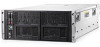
Remove the access panel 1. Release the access panel latch. 2. Slide the access panel back about 1.5 cm (0.5 in). 3. Lift and remove the access panel. NOTE: Turn the access panel over to locate the hood labels. These labels provide information on installing various options, flexible memory configurations, LED status indicators, and switch settings. Install the access panel WARNING: To reduce the risk of personal injury from hot surfaces, allow the drives and the internal system components to cool before touching them. CAUTION: To prevent damage to electrical components, properly ground the node before beginning any installation procedure. Improper grounding can cause ESD. CAUTION: Do not operate the chassis with the access panel open or removed. Operating the chassis in this manner results in improper airflow and improper cooling that can lead to thermal damage. To install the component: 1. Place the access panel on top of the chassis. 2. Slide the access panel toward the front of the chassis. The access panel locks into position. Safety considerations Before performing service procedures, review all the safety information. Removal and replacement procedures 34
-
 1
1 -
2
-
3
-
4
-
5
-
6
-
7
-
8
-
9
-
10
-
11
-
12
-
13
-
14
-
15
-
16
-
17
-
18
-
19
-
20
-
21
-
22
-
23
-
24
-
25
-
26
-
27
-
28
-
 29
29 -
 30
30 -
 31
31 -
 32
32 -
 33
33 -
 34
34 -
 35
35 -
 36
36 -
 37
37 -
 38
38 -
 39
39 -
40
-
41
-
42
-
43
-
44
-
45
-
46
-
47
-
48
-
49
-
50
-
51
-
52
-
53
-
54
-
55
-
56
-
57
-
58
-
59
-
60
-
61
-
62
-
63
-
64
-
65
-
66
-
67
-
68
-
69
-
70
-
71
-
72
-
73
-
74
-
75
-
76
-
77
 |
 |
