HP ProLiant SL4545 HP ProLiant SL4500 Series Chassis Maintenance and Service G - Page 48
Removing the fan connector ear pin
 |
View all HP ProLiant SL4545 manuals
Add to My Manuals
Save this manual to your list of manuals |
Page 48 highlights
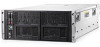
Removing the fan connector ear pin To remove the component: 1. Power down the nodes ("Power down the node" on page 30). 2. Disconnect the cable management arm. 3. Disconnect all cables from the rear of the chassis. 4. To reduce the weight of the chassis, remove the following components: a. Power supplies (on page 37) b. System fans (on page 36) c. I/O modules ("I/O module" on page 38) d. Management module (on page 37) e. Drives (on page 43) 5. Place the chassis on a flat, level surface. 6. Disconnect the fan cable from the fan connector ear pins. o 1 node chassis Removal and replacement procedures 48
-
 1
1 -
2
-
3
-
4
-
5
-
6
-
7
-
8
-
9
-
10
-
11
-
12
-
13
-
14
-
15
-
16
-
17
-
18
-
19
-
20
-
21
-
22
-
23
-
24
-
25
-
26
-
27
-
28
-
29
-
30
-
31
-
32
-
33
-
34
-
35
-
36
-
37
-
38
-
39
-
40
-
41
-
42
-
 43
43 -
 44
44 -
 45
45 -
 46
46 -
 47
47 -
 48
48 -
 49
49 -
 50
50 -
 51
51 -
 52
52 -
 53
53 -
54
-
55
-
56
-
57
-
58
-
59
-
60
-
61
-
62
-
63
-
64
-
65
-
66
-
67
-
68
-
69
-
70
-
71
-
72
-
73
-
74
-
75
-
76
-
77
 |
 |

Removal and replacement procedures
48
Removing the fan connector ear pin
To remove the component:
1.
Power down the nodes ("
Power down the node
" on page
30
).
2.
Disconnect the cable management arm.
3.
Disconnect all cables from the rear of the chassis.
4.
To reduce the weight of the chassis, remove the following components:
a.
Power supplies (on page
37
)
b.
System fans (on page
36
)
c.
I/O modules ("
I/O module
" on page
38
)
d.
Management module (on page
37
)
e.
Drives (on page
43
)
5.
Place the chassis on a flat, level surface.
6.
Disconnect the fan cable from the fan connector ear pins.
o
1 node chassis