HP R1500 HP UPS R5000 User Guide - Page 9
REPO port, The REPO feature shuts down UPS units operating under either utility or battery power. - ups manual software
 |
View all HP R1500 manuals
Add to My Manuals
Save this manual to your list of manuals |
Page 9 highlights
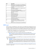
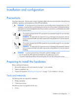
Item 1 2 3 4 5 6 7 8 9 10 11 12 13 14 Description ERM connector for the small plug on the split ERM cable Load segment 1 circuit breaker (controls the C19 and C13 receptacles, but does not control the large output receptacle) Load segment 1 (two IEC-320-C19 receptacles and two IEC-320-C13 receptacles) Cord retention clip attachment locations Load segment 2 (two IEC-320-C19 receptacles and two IEC-320-C13 receptacles) REPO port USB communications port Serial communications port HP UPS Network Module Ground bonding screw Input power line cord with NEMA L6-30 plug (NA/JPN) or IEC-309-32A plug (INTL) Load segment 2 circuit breaker Large output NEMA L6-30R receptacle (NA/JPN) or IEC-309-32A receptacle (INTL) associated with load segment 1 ERM connector for the large plug on the split ERM cable REPO port The UPS includes an isolated REPO port. When properly wired, the REPO feature enables the power at the UPS output receptacles to be switched off from a remote location. To use this feature, the REPO port must be connected to a remote, normally open switch (not supplied). The REPO switch is used in conjunction with a main disconnect device that removes the AC source from the input of the UPS. When the switch is closed: • The REPO feature immediately powers down protected devices and does not utilize the orderly shutdown procedure initiated by power management software. • The REPO feature shuts down UPS units operating under either utility or battery power. NOTE: If the UPS was operating on battery power when the remote switch was closed, no power is available to the load devices until utility power is restored and the UPS has been manually powered up. To restore power to the load devices after the REPO feature is activated, press the On button after the AC source is reconnected to the UPS. IMPORTANT: Pressing and holding the On button without utility present normally initiates a battery start and the UPS assumes the load. However, if the On button is pressed and a REPO is detected, battery start is inhibited and the UPS is not able to assume the load. The electronics module fan spins and the General Alarm LED and an audible alarm are active as long as the On button is held. To power down the entire network in the event of an emergency, the REPO ports of multiple UPS units can be connected to a single switch. Component identification 9
-
 1
1 -
2
-
3
-
 4
4 -
 5
5 -
 6
6 -
 7
7 -
 8
8 -
 9
9 -
 10
10 -
 11
11 -
 12
12 -
 13
13 -
 14
14 -
15
-
16
-
17
-
18
-
19
-
20
-
21
-
22
-
23
-
24
-
25
-
26
-
27
-
28
-
29
-
30
-
31
-
32
-
33
-
34
-
35
-
36
-
37
-
38
-
39
-
40
-
41
-
42
-
43
-
44
-
45
-
46
-
47
-
48
-
49
-
50
-
51
-
52
-
53
-
54
-
55
-
56
-
57
-
58
-
59
-
60
-
61
-
62
 |
 |
