HP Server rp8420 HP 9000 rp8420 Server - User Service Guide, Fifth Edition - Page 146
Removing and Replacing a Processor Turbo-Cooler Fan, Removing a Turbo-Cooler Fan
 |
View all HP Server rp8420 manuals
Add to My Manuals
Save this manual to your list of manuals |
Page 146 highlights
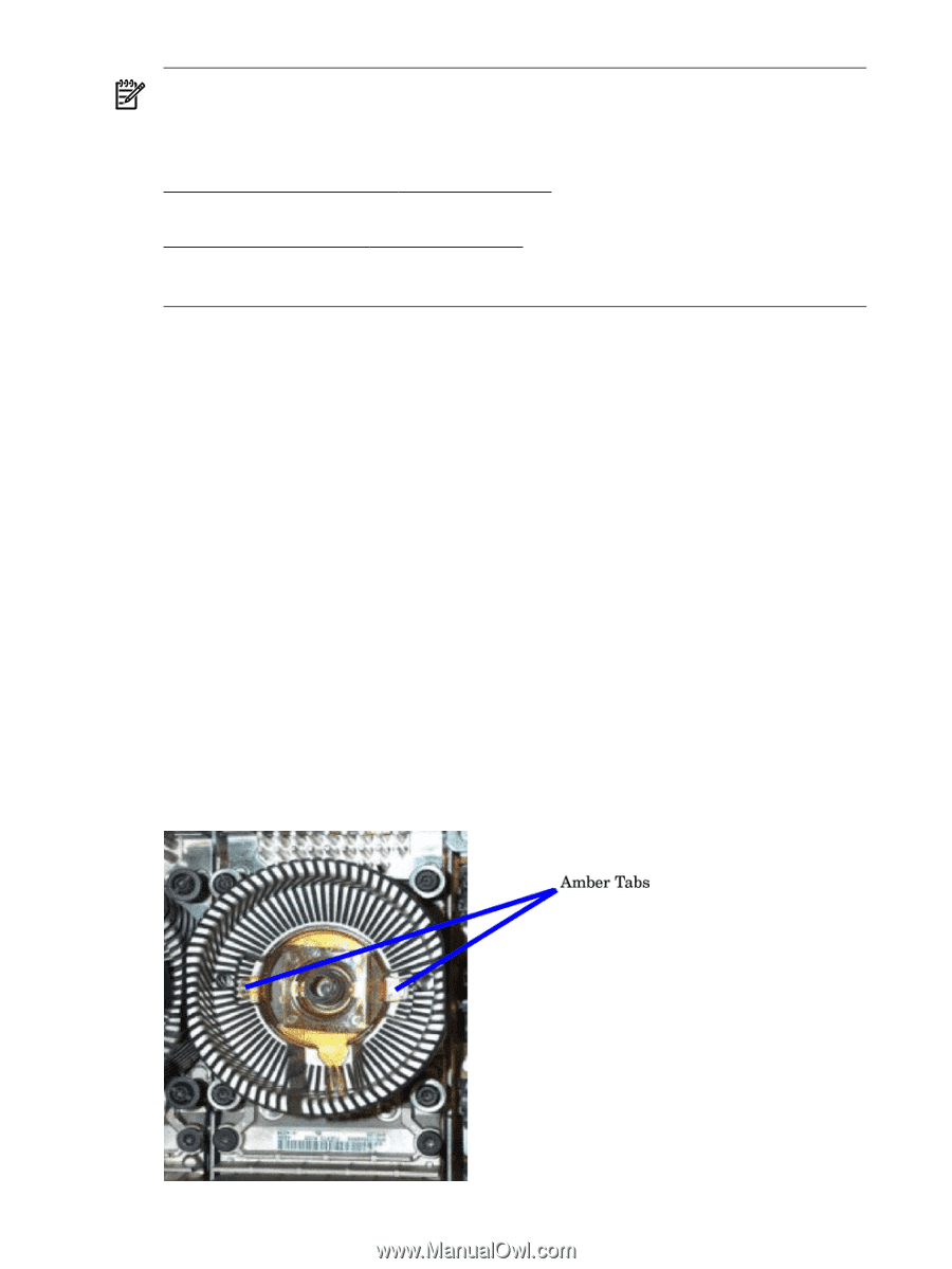
NOTE: If the firmware or programmable hardware versions are not at or above the minimum versions, go to one of the following websites to obtain the latest Firmware Release Notice and firmware patches: Internal web site: ftp://hpatlse.atl.hp.com/firmware_patches/hp/cpu External web site: ftp://ftp.itrc.hp.com/firmware_patches/hp/cpu The Firmware Update Release notice is included in the download bundle and includes the upgrade instructions. 23. Power up the nPartition. See Appendix E 'Operating System Boot and Shutdown' for details. 24. Use the MP>PS: command to verify proper operation of the cell board. Removing and Replacing a Processor Turbo-Cooler Fan The processor turbo-cooler fans are located on the cell boards. Removing a Turbo-Cooler Fan 1. Prepare an ESD safe work surface large enough to accommodate the cell board. 2. Identify the partition and cell to be removed. 3. Power down the nPartition and remove the cell with the fan to be replaced following the instructions found in "Removing and Replacing a Cell Board" on (page 117). 4. Place the cell board on the ESD safe work surface. 5. If necessary, loosen the four captive screws that secure the DIMM cover, remove the cover and set it aside. 6. If so equipped, loosen the captive screws on the CPU cover, remove the cover and set it aside. 7. Identify the CPU turbo-cooler fan to be removed and unplug the fan power cord from the cell board. 8. By inserting a screwdriver or pen between the fan blades, gently depress the two amber tabs underneath. Once the two tabs are depressed the fan will pop up. See Figure 6-37. Figure 6-37 Heatsink with Turbo-Cooler Fan Removed 146 Removal and Replacement
-
 1
1 -
2
-
3
-
4
-
5
-
6
-
7
-
8
-
9
-
10
-
11
-
12
-
13
-
14
-
15
-
16
-
17
-
18
-
19
-
20
-
21
-
22
-
23
-
24
-
25
-
26
-
27
-
28
-
29
-
30
-
31
-
32
-
33
-
34
-
35
-
36
-
37
-
38
-
39
-
40
-
41
-
42
-
43
-
44
-
45
-
46
-
47
-
48
-
49
-
50
-
51
-
52
-
53
-
54
-
55
-
56
-
57
-
58
-
59
-
60
-
61
-
62
-
63
-
64
-
65
-
66
-
67
-
68
-
69
-
70
-
71
-
72
-
73
-
74
-
75
-
76
-
77
-
78
-
79
-
80
-
81
-
82
-
83
-
84
-
85
-
86
-
87
-
88
-
89
-
90
-
91
-
92
-
93
-
94
-
95
-
96
-
97
-
98
-
99
-
100
-
101
-
102
-
103
-
104
-
105
-
106
-
107
-
108
-
109
-
110
-
111
-
112
-
113
-
114
-
115
-
116
-
117
-
118
-
119
-
120
-
121
-
122
-
123
-
124
-
125
-
126
-
127
-
128
-
129
-
130
-
131
-
132
-
133
-
134
-
135
-
136
-
137
-
138
-
139
-
140
-
 141
141 -
 142
142 -
 143
143 -
 144
144 -
 145
145 -
 146
146 -
 147
147 -
 148
148 -
 149
149 -
 150
150 -
 151
151 -
152
-
153
-
154
-
155
-
156
-
157
-
158
-
159
-
160
-
161
-
162
-
163
-
164
-
165
-
166
-
167
-
168
-
169
-
170
-
171
-
172
-
173
-
174
-
175
-
176
-
177
-
178
-
179
-
180
-
181
-
182
-
183
-
184
-
185
-
186
-
187
-
188
-
189
-
190
-
191
-
192
-
193
-
194
-
195
-
196
-
197
-
198
-
199
-
200
-
201
-
202
-
203
-
204
-
205
-
206
-
207
-
208
-
209
-
210
-
211
-
212
-
213
-
214
-
215
 |
 |